
AT32F413-based FOC driver
update log:
2023-11-15 Updated with encoder baseboard added; code framework refactored based on AT motor library; PCB updated to V3.
2023-11-02 First version code completed and open-sourced.
2023-11-02 First release
project description:
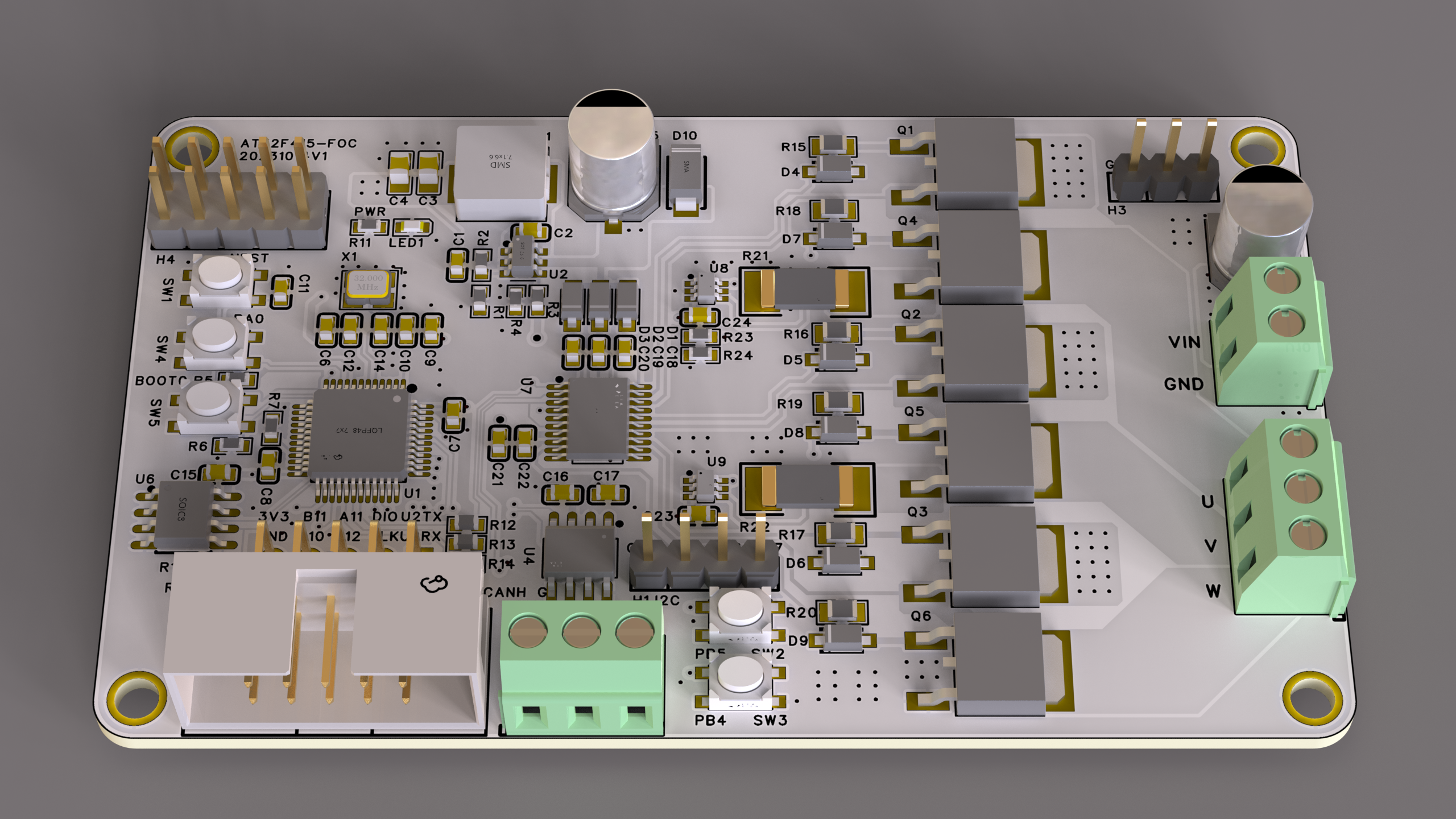
A low-cost FOC driver based on AT32F413, using FOC field-oriented control and paired with a magnetic angle sensor chip, enabling precise control of brushless DC or permanent magnet synchronous motors.
On the chip side, it uses the AT32F413 series high-performance microcontroller, equipped with a 32-bit ARM® Cortex®-M4 core, and advanced manufacturing process effectively improves overall performance to a computing speed of 200MHz. The built-in single-precision floating-point unit (FPU) and digital signal processor (DSP), along with rich peripherals and flexible clock control mechanisms, can meet the needs of various application fields. The sophisticated memory design supports up to 256KB of Flash memory and 64KB of SRAM, with its Flash memory exhibiting superior zero-wait performance, surpassing the level of comparable chips in the industry. It
features
a fully domestically produced solution, with nearly 100% domestically sourced components (capacitors and resistors can be replaced with domestically produced ones).
Utilizing the AT32F413 chip with an M4F core and integrated FPU, it achieves high-speed computation. For lower cost, the AT32F415 can be used, directly replacing the AT32F413.
This device features current sampling with a 20kHz current loop, enabling a dual-loop
low-end current sampling scheme for both speed and current. It utilizes the TP181 current sampling chip
with a CAN communication interface, an onboard EEPROM for parameter storage
, and SPI/I2C interfaces for connecting to an encoder chip to read data.
The chip
configuration includes: Main controller: AT32F413CBT7
; Power supply: MT2492 (for microcontroller power);
Pre-driver: EG2133;
CAN: SIT65HVD230DR
; EEPROM: AT24C02 (Ingenic);
MOS: NCE3080K;
Encoder (installed on the motor, for reference only): MT6701.
Limiting parameters
: Power supply voltage: 16V;
Maximum power: 83W.
Soldering instructions:
None; solder according to the BOM.
Open
source code: https://gitee.com/fhcloud/f413_foc.
The program uses Keil. Compiling AC6 requires installing Keil, then downloading the AT32F413 firmware library. Place the program and template directories together, then compile and run.
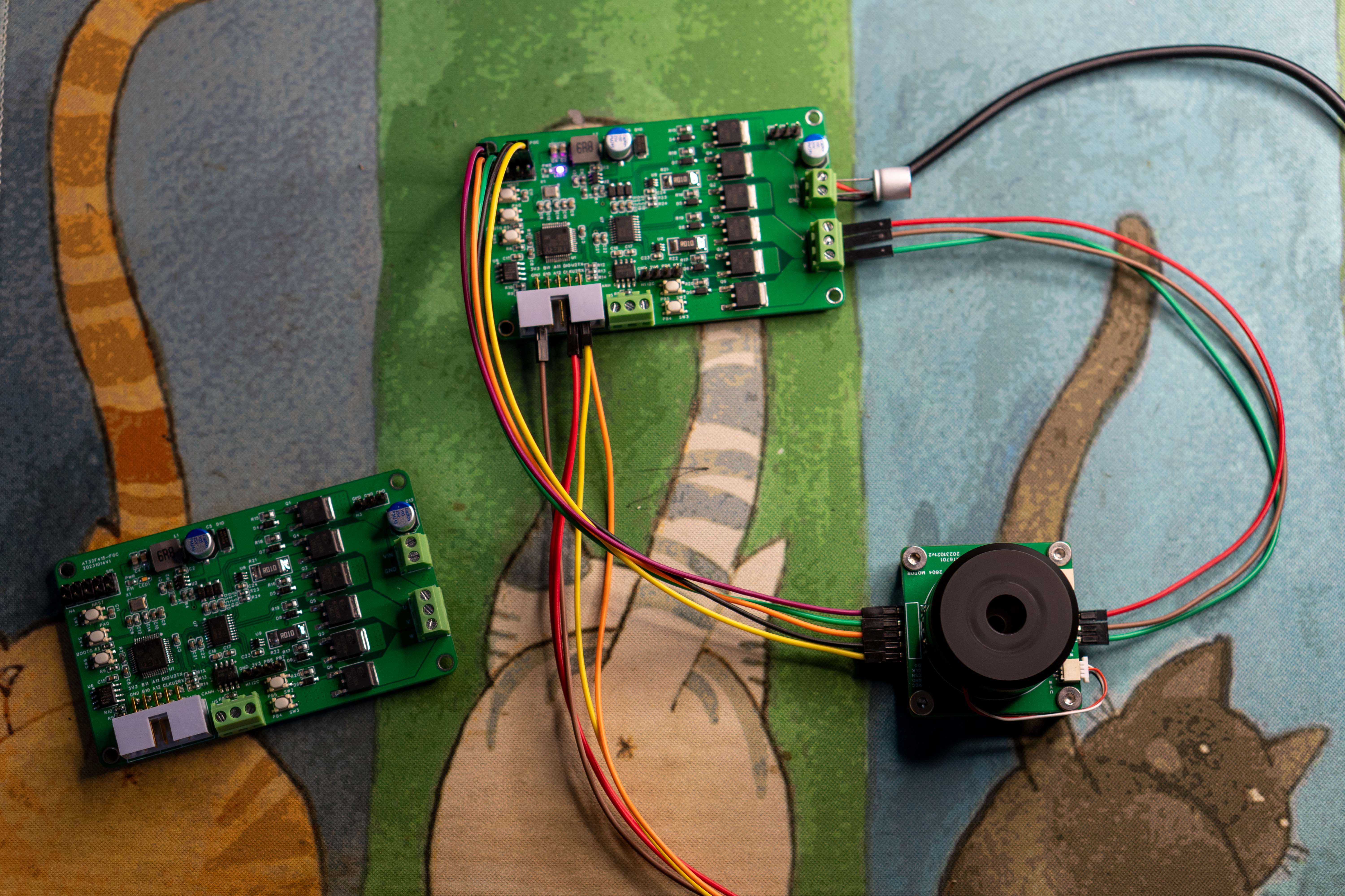
Regarding the motor
, currently only sensor-based algorithms are supported. A magnetic encoder needs to be installed on the motor to read the angle. The MT6701/MT6816 is recommended, using SSI/SPI to read angle data for high-speed control.
The video uses a 2804 motor; you can search for and purchase it on Xianyu (a Chinese online marketplace).
The subsequent development plan
includes adding sensorless control to achieve sensorless motor operation.
This involves refactoring the framework, adjusting existing code, developing
a host computer for multi-motor control, and implementing online parameter tuning.
The CAN component development
and EEPROM parameter storage component development have been completed.
Demonstration videos are available at
: [https://www.bilibili.com/video/BV1TG411C75b/](https://www.bilibili.com/video/BV1284y1R7oQ/?spm_id_from=333.999.0.0 ) [
https://www.bilibili.com/video/BV1Qw411F7Dx/?spm_id_from=333.999.0.0 )
[https://www.bilibili.com/video/BV1kQ4y1p7Sp/](https://www.bilibili.com/video/BV1KQ4y1p7Sp/ )
[
https://www.bilibili.com/video/BV1T84y1d7jM/](https://www.bilibili.com/video/BV1T84y1d7jM/)
Test screenshots and current
sampling result
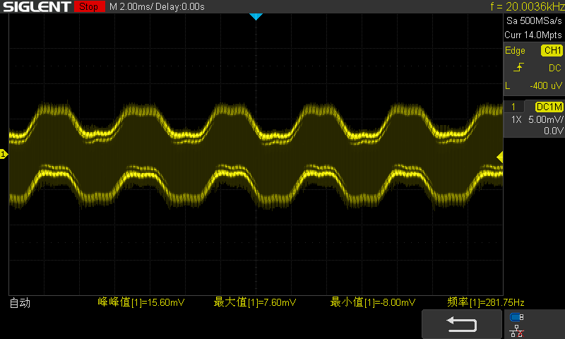
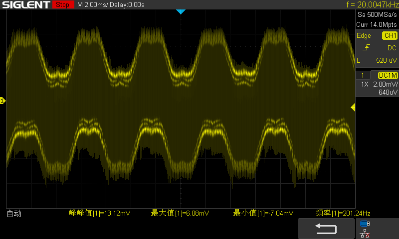
images are also available.


PDF_AT32F413-based FOC driver.zip
Altium_AT32F413-based FOC driver.zip
PADS_AT32F413-based FOC driver.zip
BOM_AT32F413-based FOC driver.xlsx
91443
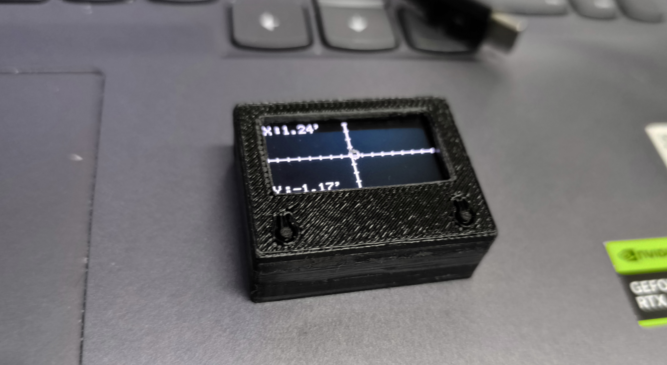
Digital Level
Function Overview:
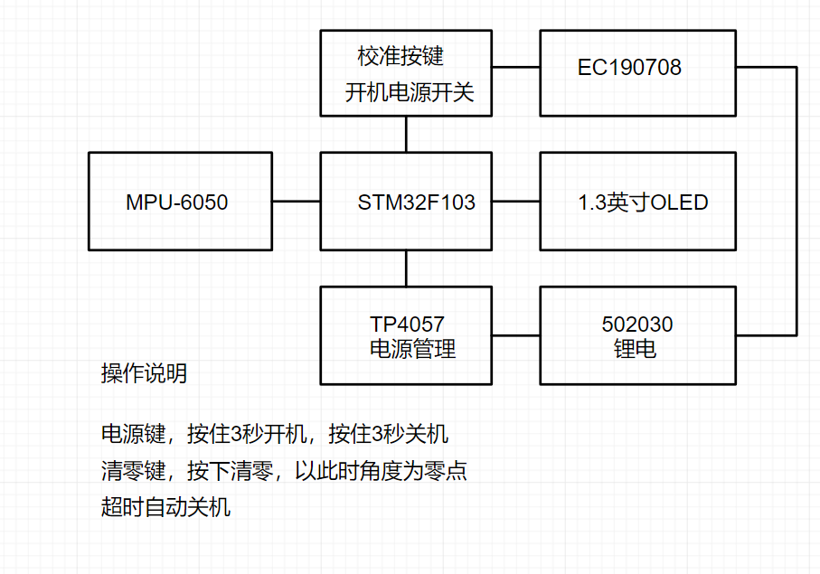
Left side calibration button: press once to zero the instrument on the current plane, press again to reset.
Right side power button: press and hold for 3 seconds to turn on/off.
Automatic shutdown after prolonged inactivity (approximately 5 minutes) .
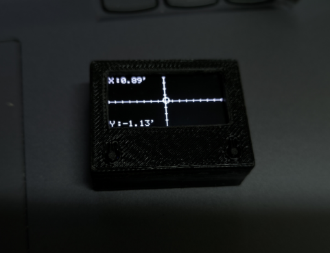
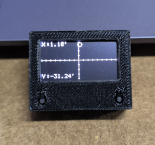
Scale graduations: one division represents 8 digits; X represents pitch angle, Y represents roll angle.
STM32-based digital level indicator

function overview:
Left calibration button: press once to set the current plane as the zero point, press again to reset.
Right power button: press and hold for 3 seconds to turn on/off.
Automatic shutdown after prolonged inactivity (approximately 5 minutes) .
Scale graduations are 8 digits per division: X is pitch angle, Y is roll angle.
A red light illuminates during charging, and a blue light illuminates when fully charged (right indicator light). The left power indicator light illuminates after power-on.
Hardware introduction:
Main controller: STM32F103C8T6;

Sensor: MPU6050


; Lithium battery charging; Power management: TP4057; Power-on
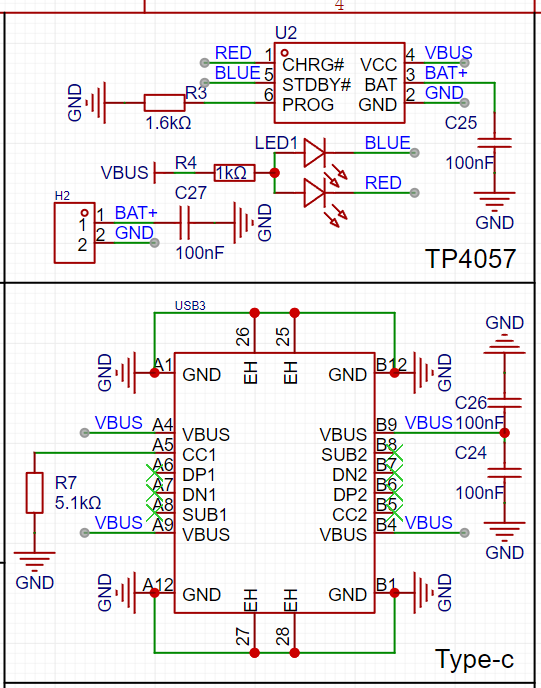
/off chip: EC190708.
Here, the EC190708 pin 3 output signal controls Q1 and Q2 MOS switches .
When there is no operation within a timeout period (PC13), the STM32-IO port outputs a high level to conduct Q3, simulating a power switch being pressed to turn off. After shutdown, PC13 is low, Q3 is off, completing the self-shutdown function.

Overall framework diagram:
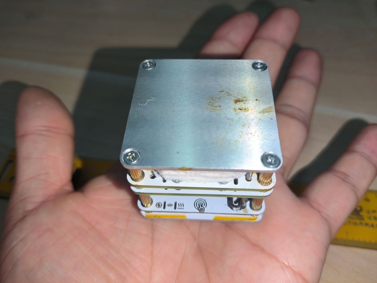
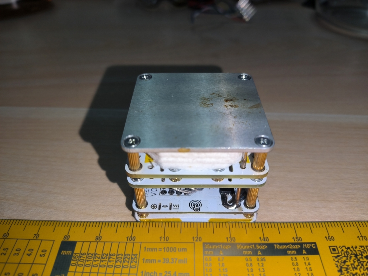
Assembly and adjustment precautions:
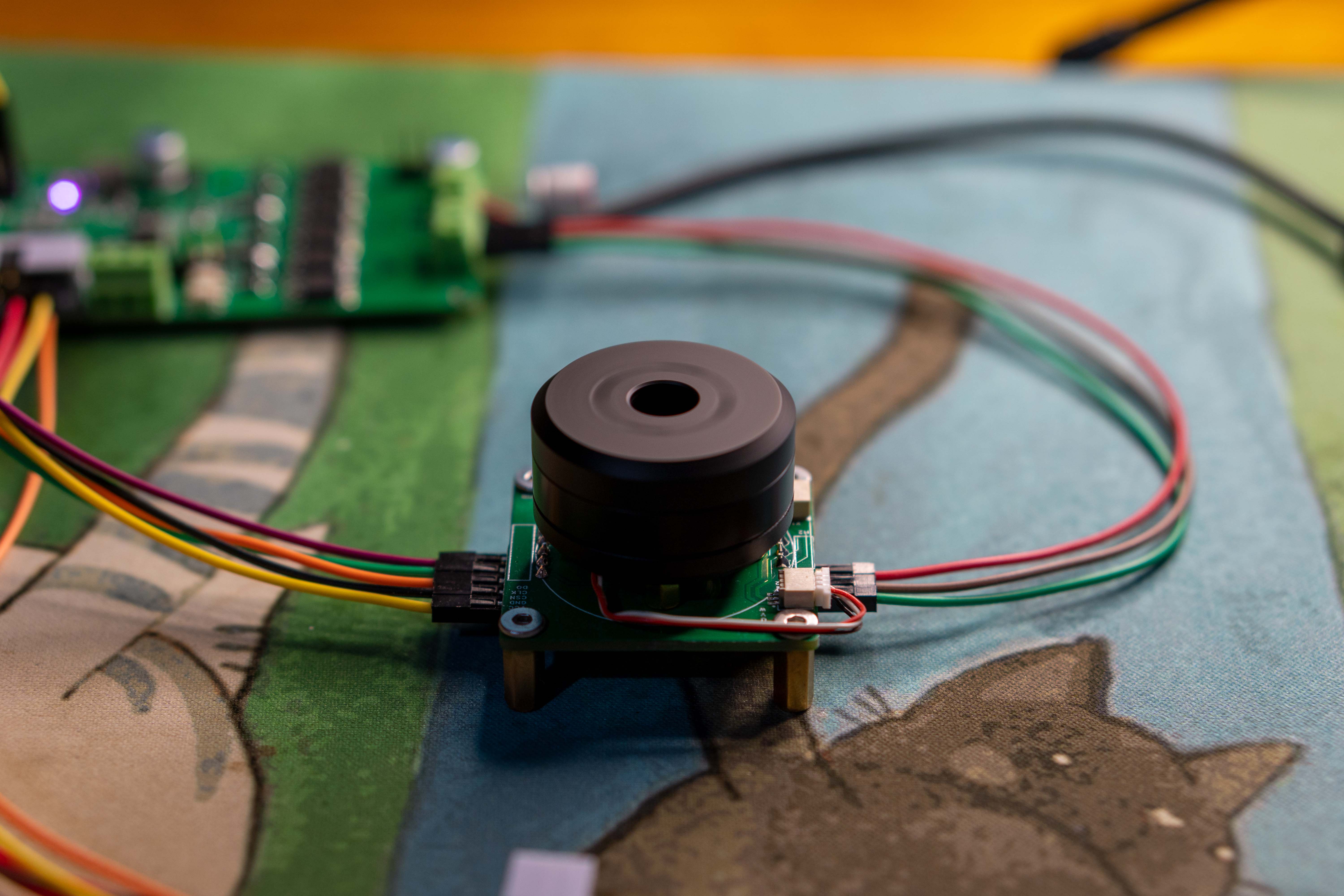
The PCB soldered finished product image

shows that both the battery and screen are glued together. If the height is insufficient during assembly, a flat material can be used as a support (here, cardboard from the JLCPCB box is used as a support; two pieces are the perfect height).

The battery model is a 502030 lithium battery with protection board leads; it is a ternary lithium battery with a single-cell voltage of 4.2V and a capacity of 250mAh.
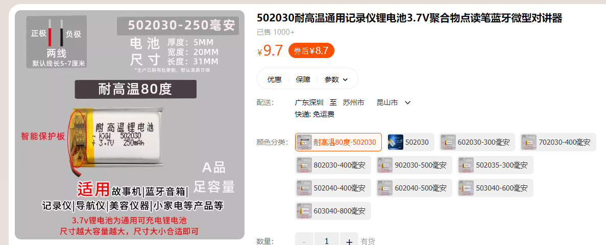
Reference link: https://detail.tmall.com/item.htm?abbucket=2&id=21166531235&ns=1&skuId=4191505948637&spm=a21n57.1.0.0
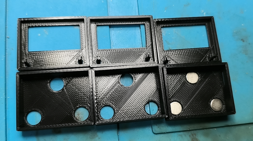
Regarding the outer casing: The outer casing is printed by JLCPCB
using FDM-3D printing. The material is black PLA;
there are no strict requirements for the printing material, as long as it is strong enough.
The upper and lower covers are connected by adhesive (502 glue).
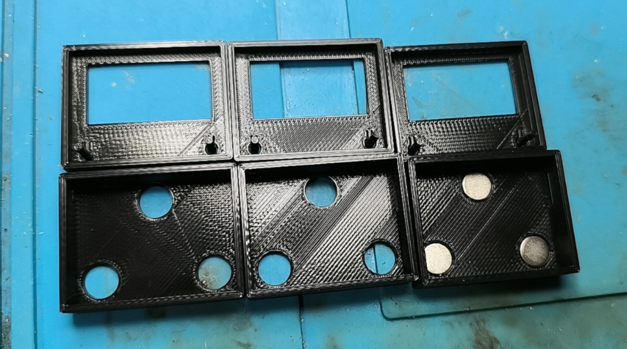
The magnet dimensions are D=8mm, H=1.5mm (8mm diameter, 1.5mm thickness, round neodymium magnet).

Reference link: https://item.taobao.com/item.htm?spm=a1z09.2.0.0.57a62e8dDPr9mH&id=615044191106&_u=a20292vc2red9d
(During installation, ensure the magnetic poles of the three magnets face the same direction.)
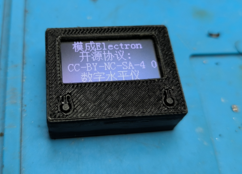
Detailed casing display:


All accessories:

Software debugging process photos:

Physical product display:

Program files are attached.
A test demonstration video has been uploaded to Bilibili; video link: https://www.bilibili.com/video/BV1fM411S7VP/?spm_id_from=333.999.0.0&vd_source=f2ecf6d07c56387a85d94b5338693a63
Digital Level.zip
PDF_Digital Level.zip
Altium Digital Level.zip
PADS_Digital Level.zip
BOM_Digital Level.xlsx
91445
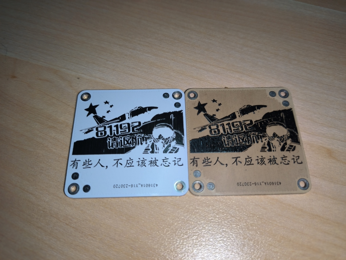
Mini heating table
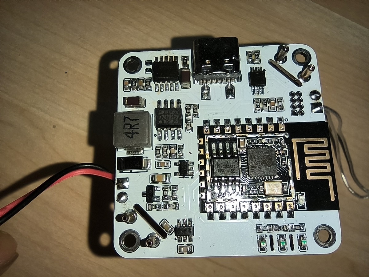
40*40mm mini heating plate, PD65W, ESP8266 main controller, WIFI control, reserved buttons and screen interface, replaceable heating plate for use as a coaster.
Mini Thermostatic Heating Platform
Engineering Connection: Mini Heating Platform
Source Code: Mini Heating Platform
Finished Product Video: Mini Heating Platform
Effect Video: Heating Effect
Background Introduction
Previously, I used a PTC heating plate for teppanyaki, but it required a 220V connection, which felt inconvenient and unsafe. Most of the time, I used small boards, and a mini heating platform was sufficient. So, I designed a mini one. Initially, I used a 333333, but found the component layout too restrictive and too small, so I switched to a 404033. The small size also presented challenges for control and display. A small screen could have been placed, but after consideration, it was removed. A touch button was placed on the front, used only for heating on/off (the actual design also included temperature adjustment and network configuration, but these were not implemented). Interfaces were retained, allowing for external I2C screens, physical buttons, and even encoders. The placement of these interfaces or the addition of a casing is left for interested parties to consider.
Features include:
WIFI control (currently AP, planned AP+STA dual mode, automatically switching AP when unable to connect to the internet, not yet implemented);
Touch button control (supports single click, double click, multi-click, long press; currently uses triple click to control the switch);
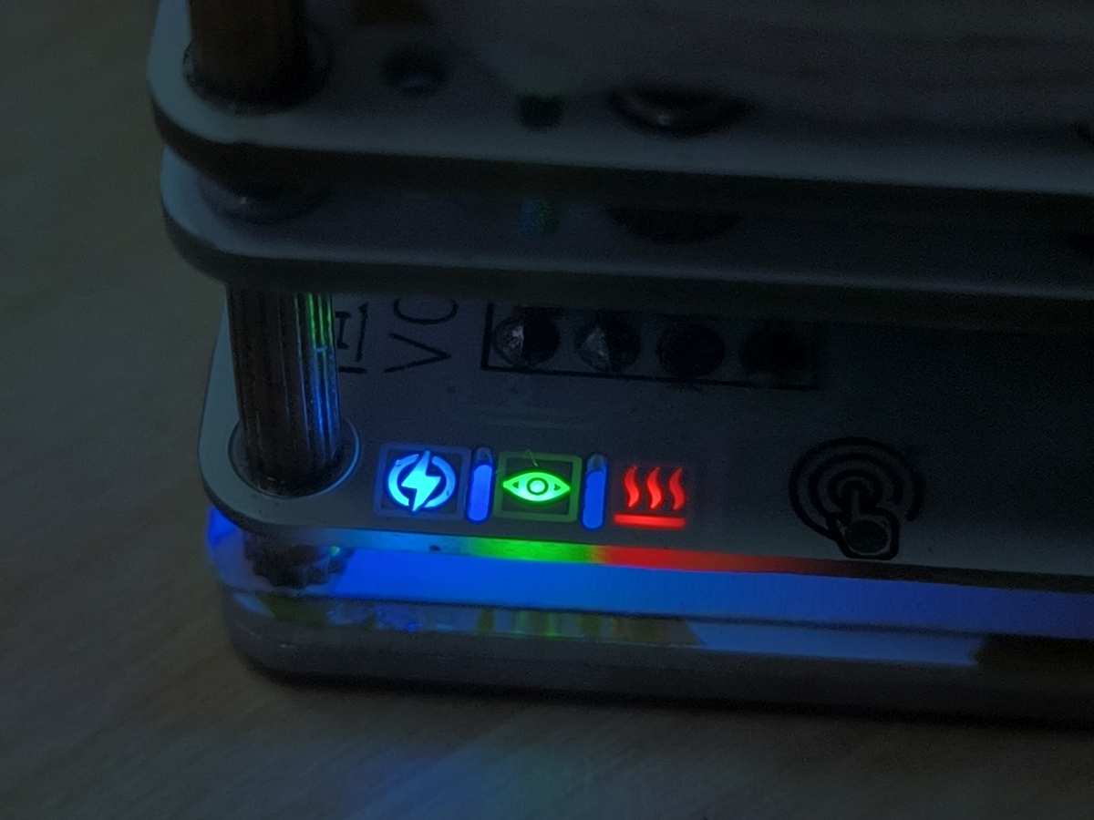
Three-light status display (power + status + heating);
PD 20V power supply (PD+QC, voltage selection is not implemented due to insufficient IO, directly uses the highest 20V voltage; if the power supply does not support 20V, it will increase to the highest supported voltage);
Maximum 50W heating (can be adjusted to 65W on the heating plate line, but this is sufficient for my needs, so I won't bother);
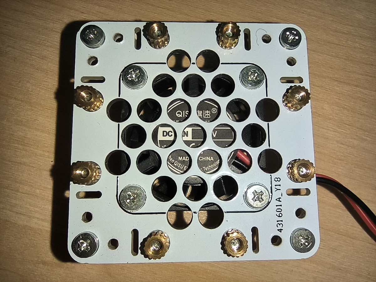
Fan-assisted cooling (probe conducts heat quickly, a fan is necessary; if the probe is replaced to optimize the heating power supply, the fan can be eliminated, but I haven't found a cost-effective probe or spring yet).
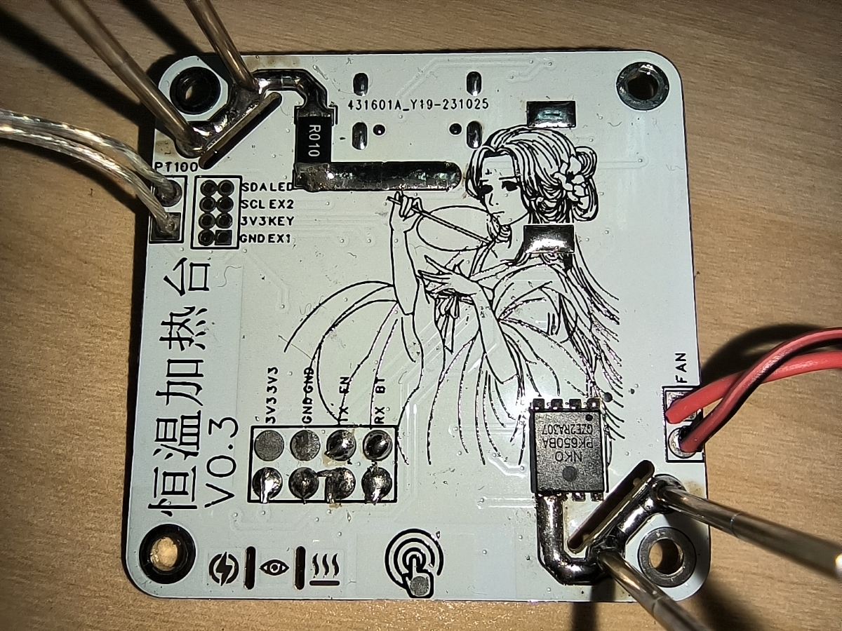
PT1000 temperature sampling (PT1000, PT1000, PT1000, don't mistake it for PT100).
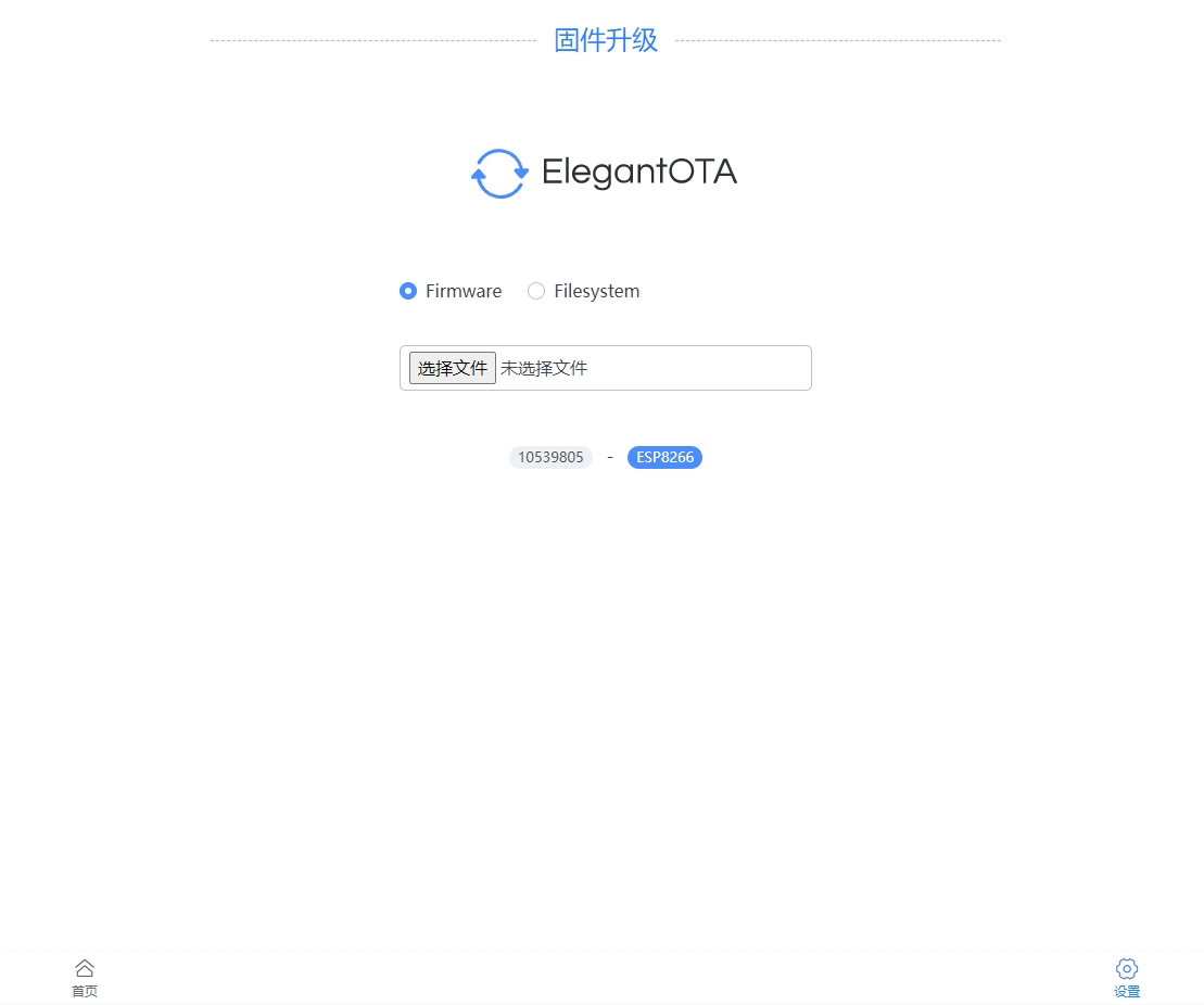
Initial serial port upgrade; subsequent upgrades can be done via network. With a serial port upgrade module, power-off upgrades are possible.
Temperature control <280℃ (280℃ is roughly the limit at 50W; the temperature can be increased further at 65W, but the heating plate solder layer can't withstand it, so it's not very useful).
Operating current and voltage display (INA226 sampling; this can be removed if not needed or to reduce costs).
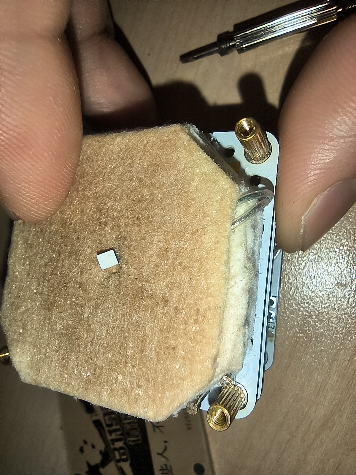
Finished product display:

internal structure
page control.
After power-on, mobile phones or computers search for Wi-Fi and connect to HeatPlatform; password: 12345678. After connecting, there are issues with accessing the configuration menu when

upgrading firmware (192.168.0.1) in the browser. Using an LDO as the temperature sampling reference source results in inaccurate temperatures, and fine-tuning has been done; the accuracy is questionable. For higher precision, a reference source could be added. I'm not very good at adjusting the PID, and temperature overshoot occurs. The PID cannot be debugged or configured via the page. Later, I'm considering adding automatic PID calibration, referencing the Marlin source code. During serial port downloads or after online upgrades and restarts, heating is accidentally activated briefly; the cause is currently unknown. The mobile browser's WebSocket connection is sometimes extremely slow, causing the page to be unusable for a period after opening. (Later, I'm considering using WebSocket for temperature display.) (Control switches back to AJAX) Automatic switching of network configuration mode is not yet implemented. In AP mode, the phone cannot connect to the external network, making it relatively troublesome to use. Manufacturing tutorial : Screws: M23 (28 pieces), M27 (4 pieces, 7-15mm are all acceptable) Copper pillars: M22.5 (8 pieces), M24 (4 pieces), M28 (4 pieces), M211 (4 pieces) Fan: 2507 or 3007, if the thickness is 10mm, it can barely fit, but the heat dissipation effect is not good. Probe: Huarong P100-H2 Torx head (or other heads, I polished the Torx head to prevent piercing the copper foil) Insulation cotton: Aluminum silicate fiber paper (not as sharp as fiberglass, but still has a small number of needle-like crystals, use with care) Other components as originally For PCB prototyping, select three lines for drawing. The control board should be 1.0mm thick, and the others 1.6mm. Other lines are unnecessary . Compilation tools: VS Code + PlatformIO (Arduino can also be used; the required library files are in the lib_deps file of platformio.ini in the root directory, but this has not been tested). Download tool: TTL serial cable. It's uncertain how many people are involved, so a detailed tutorial won't be provided yet. If more people join, we'll update the log later as needed. Updated 2023-11-08: Added BOM form. Products in the form are actual products used, but authenticity and lowest price are not guaranteed. Those concerned about authenticity or price should replace the form themselves.

BOM_Control Panel_Schematic2_2023-11-08.xlsx
PDF_Mini Heating Table.zip
Altium Mini Heating Table.zip
PADS_Mini Heating Table.zip
91446
LEGO Compatible Walkie-Talkie - 2023 Spark Program
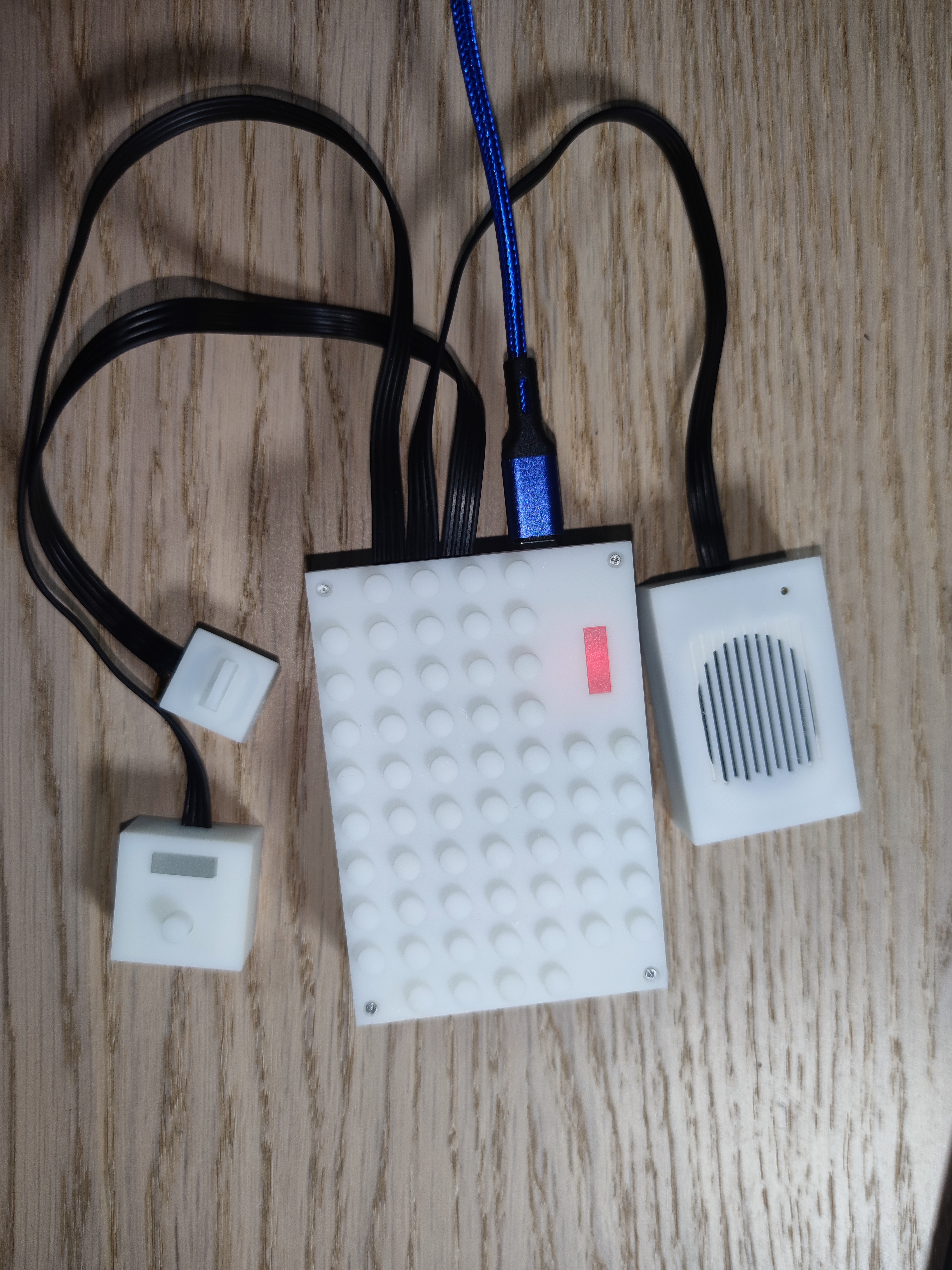
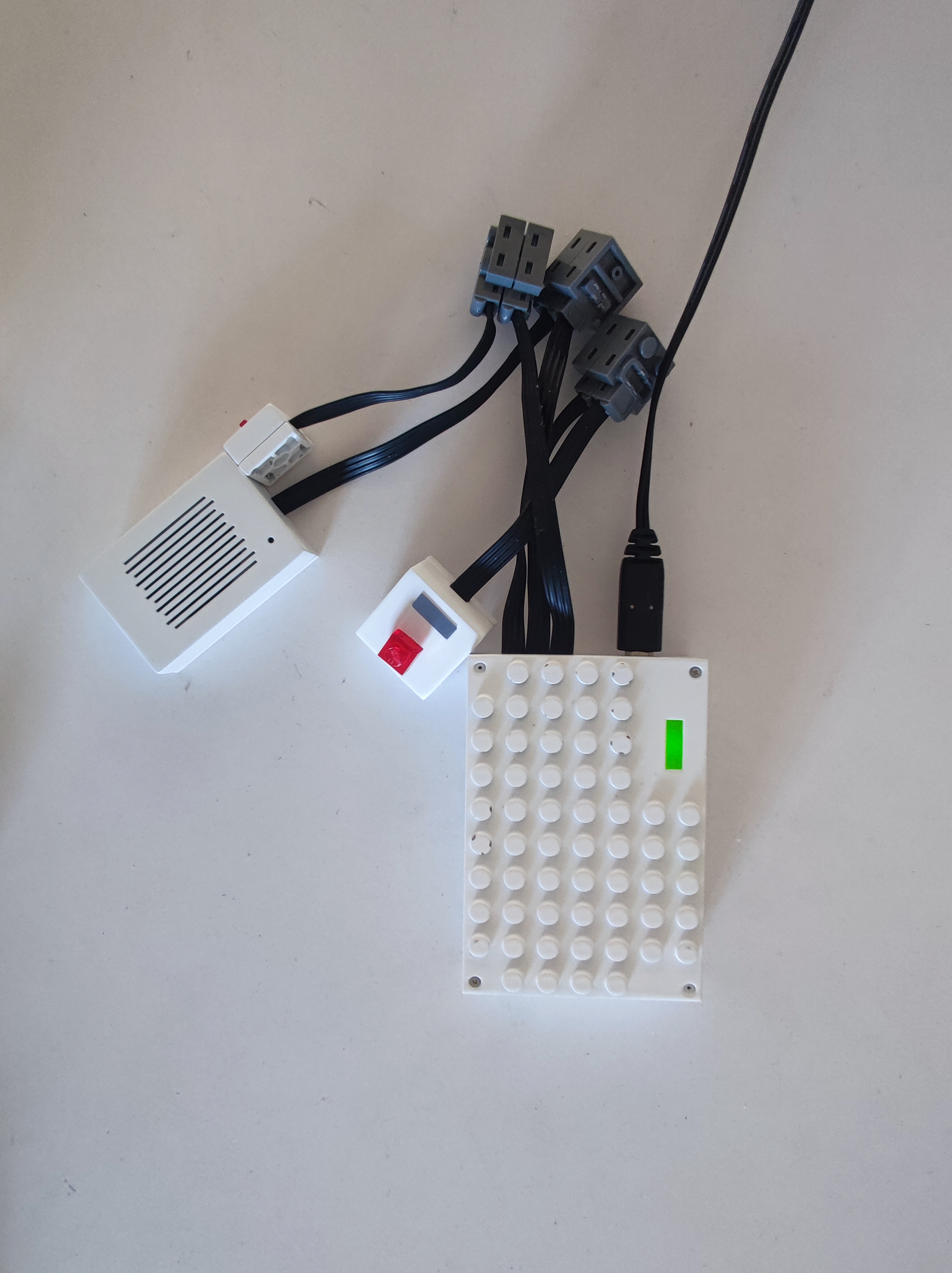
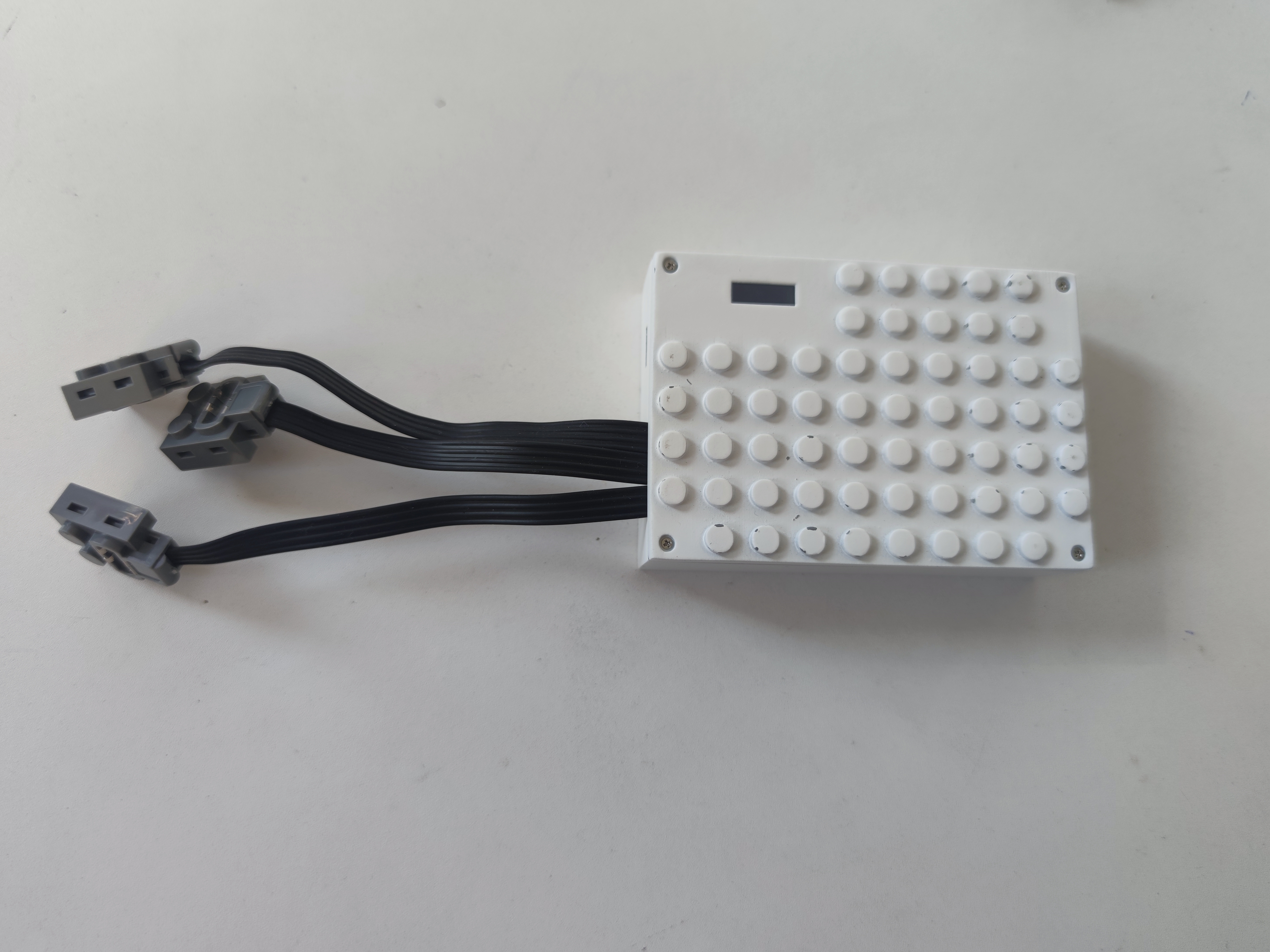
A walkie-talkie module compatible with LEGO-like building blocks, comprising a main unit module, a switch module, a speaker and microphone module, and a PTT button module.
Project Description:
This project
is a walkie-talkie module compatible with LEGO-like building blocks. It includes a main unit module, a switch module, a speaker and microphone module, and a PTT button module.
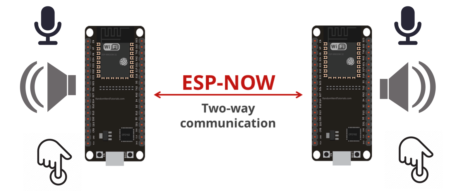
Inter-module connections use LEGO PF (Power Component) cables and communication is achieved using the Espressif ESP32 2.4G module.
Open Source
License:
GPL 3.0.
Project Functionality:
This is a walkie-talkie module compatible with LEGO-like building blocks. It includes a main unit module, a switch module, a speaker and microphone module, and a PTT button module.
Inter-module connections use LEGO PF cables and communication is achieved using the Espressif ESP32 2.4G module.
Project Attributes:
This is the first public release of this project, and it is my original work. This project has not won any awards in other competitions.
Project Progress
====================================================================
Every step was slow, every step was a learning experience
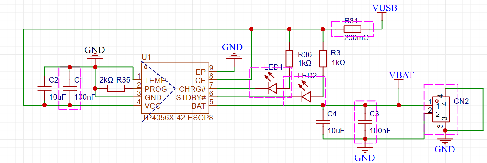
=== ... The design is complete, and the module shell design is 95% complete. Assembly accuracy testing between modules, software testing, and 3D design optimization are underway. Assembly testing is expected to be completed by October 2023. Design principles and software communication principles: The walkie-talkie utilizes the Espressif ESP-NOW protocol to achieve 2.4G voice communication between ESP32 modules in simplex mode. ESP-NOW: Utilizing the ESP-NOW protocol, it supports one-to-one, one-to-many unidirectional, many-to-one unidirectional, and bidirectional communication, and can carry a maximum payload of 250 bytes. The walkie-talkie transmits audio at a maximum of 248 bytes. Inter-module communication uses broadcast addresses; multiple devices can automatically join and receive audio upon power-on without configuration. Audio sampling: 8K 16-bit audio data . Appearance design principles: The entire walkie-talkie adopts a LEGO-style modular design, allowing for combination with LEGO-like building blocks, providing children with more fun ways to play. Modules can be extended and combined using cables from LEGO PF parts. Application Scenarios: Can be combined with LEGO toy guns to enable indoor communication and cooperative battle games between multiple children. Hardware Design Principles: Implements simplex communication like a walkie-talkie. When walkie-talkie A presses the PTT button to start a call, walkie-talkie B simultaneously receives and plays the voice. Voice reception is not supported when making external calls (this can be optimized to full-duplex communication via code). MCU: ESP32-WROVER-IE-N8R8 Download Circuit: CH340C LDO: HOLTEK HT7833 Charging: TP4056X-42-ESOP8, 1000mA 523450 lithium battery, 2kΩ charging resistor, 580mA current Codec: Everest-semi ES8311 single-channel ADC/DAC for microphone voice capture and audio playback processing Power Amplifier: Nsiway NS4150B ultra-low EMI, filterless 3W mono Class D audio power amplifier, compatible with 4Ω 3W and 8Ω 2W Speaker: 4Ω 3W Microphone: C529894 INGHAi GMI4015P-30DB Software Components: ESP-ADF V2.4 ESP-IDF V4.4 The Espressif ESP-ADF audio component implements audio reading and playback. The Espressif ESP-ADF provides PTT button press detection and recognition, as well as callback ADF Battery_service. It provides battery monitoring and low battery alarm audio processing logic in conjunction with the hardware design. It follows three audio paths: (1) Voice information sent by the microphone: [Mic]-->[i2s_stream_reader]-->[raw_reader]--[espnow_send] (2) Voice received by espnow and played back: [espnow_receive]-->[raw_writer]-->[i2s_stream_writer]-->[speaker] (3) Prompt tone playback path (welcome message + low battery reminder): [tone]-->[mp3_decoder]-->[filter_sample]-->[i2s_stream_writer]-->[speaker] The switching of the audio playback path is achieved by ADF pipeline break + relink. Physical demonstration: 3D printed version without paint . Red light is displayed during charging. Design Considerations for a Full Charge Green Light : 1. The power monitoring section does not use a fuel gauge chip, so power estimation may be inaccurate. 2. The charging current can be adjusted using the RPROG resistor . 3. The power supply to the download circuit is disconnected and unsoldered by default. When downloading is needed, you can short-circuit the two 2.54 PIN ports with a jumper to reduce standby power consumption. 4. The notification tone needs to be programmed separately. Refer to the following command: C:UsersABC.espressifpython_envidf4.4_py3.8_envScriptspython.exe C:UsersABCespesp-adfesp-idfcomponentsesptool_pyesptoolesptool.py --chip esp32 --port com6 --baud 921600 --before default_reset --after hard_reset write_flash -z --flash_mode dio --flash_freq 40m --flash_size detect 0x110000 ./tone/audio_tone.bin


5. Text-to-speech tool: https://www.text-to-speech.cn/
Other
Gitee open-source code: https://gitee.com/dezlab/lego-walkie-talkie
Full Bilibili demo video: https://b23.tv/PJ4bQ49
https://b23.tv/Twpw6f5
PCB Verification.mp4
3D printed shell STL.7z
Finished Product Communication Verification.mp4
PDF_LEGO Compatible Brick Walkie Talkie--2023 Spark Program.zip
Altium_LEGO Compatible Walkie-Talkie--2023 Spark Project.zip
PADS_LEGO Compatible Walkie-Talkie--2023 Spark Project.zip
BOM_LEGO Compatible Brick Walkie Talkie--2023 Spark Program.xlsx
91447
electronic


 京公网安备 11010802033920号

 1N5261AURTRE3


