The 3D-printed shield is just enough to build a Voron 0 with the most basic functions. If you want to add more interfaces, you'll need to use it with a Raspberry Pi expansion cap. Connecting two printed shields should also work if you're using Klipper.
The V0 Simple Display has also been redrawn, using the same component positions for compatibility.
The 3D-printed shield
design is inspired by Protoneer's CNC Shield and the RepRap project's Arduino Mega Pololu Shield (RAMPS) (perhaps this board could be called the Arduino Uno Pololu Shield?).
This expansion shield is designed for use with the Arduino Uno R3, but theoretically it should be compatible with any development board using Uno-sized sockets. Many official MCU development boards support the Arduino pin layout (such as Renesas and STMicroelectronics).
To be compatible with both 3.3V and 5V development boards, it is powered via the IOREF interface on the Uno R3. This interface may not be present on some very old Uno development boards, so the external power input pad in the upper right corner can be used.
Development boards using Type-B interfaces (large square pins) may experience interference with MOSFETs. However, many Uno boards now use Micro-B or Type-C. Slightly moving the soldered MOS positions might eliminate interference. If that doesn't work, you can remove the Type-B interface and communicate directly using the Arduino's serial port (pins 0 and 1).
This design is primarily for Klipper, but other programs should also be compatible.
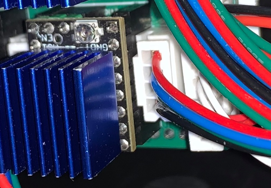
The TMC2209 stepper motor driver module is highly recommended. To save I/O, the En pins of all stepper motor drivers are fixed to GND to make them default to the ON state. The TMC2209 can control the driver's on/off state via a single-wire serial port instead of the En pin, so it can be turned off when not in use.
Additionally, the 3D printed shield does not have a power supply function, so separate power supplies are needed for the development board and Raspberry Pi. The 3D printed
shield's I/O interfaces are as follows:
Arduino Uno size-compatible header;
4 sockets compatible with Pololu stepper motor driver module pins;
2 heater interfaces;
2 fan interfaces;
3 limit switch interfaces (multiplexed with soft limit) ;
2 thermistor interfaces
. Please refer to the silkscreen on the PCB for the specific location of each interface.
Jumper settings
at the stepper motor driver location control functions such as microstepping and serial port control. The jumper numbers are as follows:
10
7
4
1
11
8
5
2
12
9
6
3.
Jumpers 6 and 3 are soft limit jumpers, jumpers 12 and 9 are serial port jumpers, and the remaining positions have different functions depending on the driver module used.
Using the serial port to control the TMC2209 driver module (recommended):
When using the TMC2209 driver module and configuring it via serial port, you first need to connect the serial port jumper cap. Some modules require the jumper cap to be connected to 11-12, some to 8-9, and some can use both; the specific connection depends on the design of the driver module.
Additionally, when inserting more than one TMC2209 module, you also need to set the serial port address for the module via jumpers, and it is best to set a different serial port address for each module to facilitate issuing different settings to different modules.
Address
jumpers
0 and 1-2 are
not inserted . When using the TMC2209 and serial control, soft limit functionality ( i.e. , no limit to zero) can be used for the three stepper motor drivers numbered 0 , 1, and 2. Connecting jumpers 3-6 of the corresponding module will connect the DIAG pin used for soft limit to the limit circuit. However, after connecting the soft limit jumpers, limit switches should not be connected to the corresponding interfaces. Other driver modules (not recommended): When the stepper motor driver does not support serial communication (e.g., A4988) or operates in Standalone mode, the bottom row of pins (3, 6, 9, and 12) should not be used. In this case, jumper caps should first be inserted on pins 10 and 11, and then other jumper caps should be inserted according to the microstepping settings used. Microstep jumper settings : Full step without inserting half step 1-2 4-minute 4-5 8-minute 1-2 and 4-5 16-minute 1-2, 4-5 , 7-8. For detailed firmware compilation instructions , please refer to the Klipper documentation. Generally, the main steps are: Enter the Klipper directory and access the compilation configuration interface : `cd ~/klipper/ ` `make` `makeconfig` Select the microcontroller used and configure it. Enter `make` to compile. Flash the compiled results to the microcontroller. (Sometimes this can be combined with step three.) The flashing method varies depending on the development board and microcontroller used; please refer to the corresponding device's instructions for specific operations. For ATmega328P, configuring the compilation toolchain version higher than Buster's Debian distribution has an AVR compilation toolchain issue, preventing compilation for ATmega328P. Therefore, it is necessary to downgrade the relevant software packages before Klipper can compile firmware for ATmega328P. This solution comes from a GitHub issue. If using other development boards, you can skip this section. Add the Buster repository. Open the `/etc/apt/sources.list` file and use `sudo nano /etc/apt/sources.list`. Create a new line at the bottom and add `deb http://raspbian.raspberrypi.org/raspbian/ buster main contrib non-free rpi`. Specify the AVR toolchain version.
Create the file `sudo nano /etc/apt/preferences.d/avr-buster`
and fill in the following content: Package: avr-libc avrdude binutils-avr gcc-avr
Pin: release n=buster
Pin-Priority: 1001
Reinstall the AVR package:
`sudo apt update`
`sudo apt install avr-libc avrdude binutils-avr gcc-avr`
If you encounter software source signature issues, you can try using the following command:
`sudo apt-key adv --keyserver keyserver.ubuntu.com --recv-keys 9165938D90FDDD2E`
After cleaning with `make clean`, recompile.
For this extended shield, some useless functions (such as external ADC or sensor connection functions) should be removed during compilation to avoid the compiled file becoming too large to burn.
Raspberry Pi Zero Extension Cap:
Since the 3D printing shield only guarantees the most basic printing function, using this extension cap can provide some additional interfaces. Similarly, this expansion cap does not have a power supply function.
The provided interfaces are as follows:
1 simple screen interface,
1 5V serial port,
1 I²C interface (connected to the screen interface's I²C)
, 1 ICSP-compatible SPI interface with two additional chip select pins,
2 fan interfaces,
2 switch interfaces,
2 relay interfaces , and
7 unexposed pins (their function is unknown).
Although this expansion cap provides pins for the WS2812B LEDs on the screen, Klipper currently cannot use the Raspberry Pi's GPIO to operate the WS2812 series LEDs. However, since the pins used provide PCM and PWM functions, these can be used to control the LEDs outside of Klipper. (The PWM0 used conflicts with one of the fan interfaces. Theoretically, it can also be connected to the SPI interface for control.)
The Raspberry Pi's GPIO has built-in pull-up and pull-down modes, so resistors R7 and R8 should be usable even if omitted.
Since this is designed for use with Arduino, a circuit for level conversion to 5V is included at the serial port. If using a 3.3V development board, you can replace the GPIO pin header with an extended pin type and connect directly to the GPIO. All interfaces except the serial port use 3.3V. The Klipper
host
program (Klippy) does not provide direct GPIO manipulation functionality; therefore, using Raspberry Pi's GPIO requires compiling a Klipper program for the Raspberry Pi to run.
Using Klipper with Raspberry Pi GPIO is similar to using other microcontrollers, using `make` and `makeconfig` for configuration and compilation. When compiling for devices like Raspberry Pi, the microcontroller architecture used is Linux Process.
Besides compilation, some additional configuration for the operating system is required. Please refer to the Klipper documentation for specific instructions.
The simple screen
is modeled after the V0 Simple Display. Most other Voron screen modules have independent microcontrollers and communicate with the host computer via USB or other interfaces. This simplified screen directly connects its components to a 10-pin IDC socket, allowing it to connect to existing microcontrollers and significantly reducing costs.
The simplified screen offers the following features:
a 1.3-inch OLED I²C screen,
a rotary knob
, an emergency stop button,
and LED indicators.
When selecting an I²C screen module, pay attention to the driver chip used; a module using the SH1106 should be chosen. While an SSD1306 module can be used, it cannot set the X offset, potentially resulting in some pixels not displaying.
The rear pads are used to swap the first two pins of the OLED screen module; the default is 1-GND, 2-VCC. If the screen module is reversed, the existing wiring under the solder mask needs to be cut and connected to the other side.
It is recommended to solder the LEDs first and test them, as the Schmitt trigger used to boost the LED signal level to 5V is located below the screen; if problems occur, the screen needs to be removed, which is inconvenient.
If you plan to connect this screen to a Raspberry Pi, the Klipper cannot control the WS2812 LEDs via the Raspberry Pi's GPIO, so this step can be omitted. However, omitting the Schmitt trigger is not recommended, as it will require removing the screen if you want to add LEDs later.
For BOM procurement
, you can find similar components on the LCSC online store with a 16-15 coupon. However, pay attention to the parameters, pin information, etc. Due to the limited height of the electrical compartment
securing
the Voron 0, double-sided tape is recommended. The
Klipper configuration
file should be modified before use; do not use it directly!
[include mainsail.cfg]
# Pin mapping for Arduino 3D Print Shield
# Pin number is Arduino Uno R3, used by ATmega328P
# Default is Voron 0
## Voron 0.2 3D Print Shield config
## *** Things to check and change ***
## Microcontroller interface, in the [mcu] section
## Z-axis and extruder motor current, in the [tmc2209 stepper_*] section
## Number of steps per extruder revolution, in the [extruder] section
## Thermistor type, in the [extruder] and [heater_bed] sections - see common types at https://www.klipper3d.org/Config_Reference.html#common-thermistors
## Motor current, in the [extruder], [stepper], and [_HOME_X/Y] macro sections
## PID calibration, in the [extruder] and [heater_bed] sections
## Fine-tuning the step count of the E-stepper motor is located in the [extruder] section.
## See https://docs.vorondesign.com/build/startup/#v0 for more information
[ mcu ] ## ... Raspberry Pi GPIO control requires prior compilation and installation of Linux processes. [printer] kinematics: corexy max_velocity: 200 # Maximum XY movement speed max_accel: 2000 # Maximum XY movement acceleration max_z_velocity: 15 # Maximum Z-axis speed max_z_accel: 300 # Maximum Z-axis acceleration square_corner_velocity: 6.0 [skew_correction] ## ... Stepper Motor Settings ########################################################################### [stepper_x] step_pin: PD7 dir_pin: PD5 # Check motor direction; add ! before if reversed #enable_pin: # Driver enable pin; comment out this line when the En pin is in enabled mode rotation_distance: 40 # Distance moved per revolution microsteps: 32 # Microsteps full_steps_per_rotation: 200 # 0.9° motor set to 400, 1.8° motor set to 200 endstop_pin: tmc2209_stepper_x:virtual_endstop # Limit switch pin; automatically enable multi-MCU return if located in another MCU position_endstop: 120 # Limit switch position position_max: 120 # Maximum movement position homing_speed: 40 # Homing speed homing_retract_dist: 0 # Backward distance before secondary homing, setting to 0 disables secondary homing [tmc2209 stepper_x] uart_pin: PD3 uart_address: 1 interpolate: False # 256-step interpolation microstepping function run_current: 0.80 # Calculate the operating current using the formula (rated current * 0.707 = maximum operating current), starting from 60%-70% of the maximum value hold_current: 0.600 # Static torque holding current sense_resistor: 0.110 # Sampling resistor, no need to modify if not necessary, default value 0.110 ohms stealthchop_threshold: 0 # When the speed (mm/s) is lower than the set value, the silent chopper mode is used. Setting it to 999999 will make the driver always use silent chopper mode; setting it to 0 will use the propagation cycle mode. ` diag_pin: ^PD4` # Sensorless homing function requires shorting the DIAG jumper. `driver_SGTHRS: 85` # Maximum sensitivity for sensorless homing, maximum value is 255, requires adjustment. `[stepper_y] step_pin: PB5` ` dir_pin: PB4` # Check motor direction; if reversed, add this at the beginning!
#enable_pin: # Driver enable pin; comment out this line when the En pin is fixed in enabled mode.
rotation_distance: 40 # Distance moved in one revolution.
microsteps: 32 # Microsteps: Number of microsteps.
full_steps_per_rotation: 200 # 400 for 0.9° motors, 200 for 1.8° motors.
endstop_pin: tmc2209_stepper_y:virtual_endstop # Limit switch pin; automatically enables multi-MCU homing if located on another MCU.
position_endstop: 120 # Limit switch position.
position_max: 120 # Maximum movement position.
homing_speed: 40 # Homing speed.
homing_retract_dist: 0 # Backward distance before secondary homing; setting to 0 disables secondary homing.
[tmc2209 stepper_y]
uart_pin: PD3
uart_address: 0
interpolate: False # 256-step interpolation microstepping function
run_current: 0.80 # Calculates the operating current using the formula (rated current * 0.707 = maximum operating current), starting from 60%-70% of the maximum value
hold_current: 0.600 # Static torque holding current
sense_resistor: 0.110 # Sampling resistor; no need to modify if unnecessary, default value 0.110 ohms
stealthchop_threshold: 0 # Uses silent chopper mode when the speed (mm/s) is lower than the set value. Setting it to 999999 will make the driver always use silent chopper mode; setting it to 0 uses propagation cycle mode.
diag_pin: ^PB0 # Sensorless homing function requires short-circuiting the DIAG jumper
driver_SGTHRS: 88 # The maximum sensitivity without a sensor is 255, which needs to be adjusted
. ##
... 32 # Subdivision microstep count endstop_pin: !PC2 # Limit switch pin, automatically enables multi-MCU homing if located in another MCU #position_endstop: 119 # Limit switch position position_max: 119 # Maximum movement position position_min: -1.5 # Minimum movement position homing_speed: 20 # Homing speed second_homing_speed: 3.0 # Second homing speed homing_retract_dist: 3.0 # Backward distance before second homing, setting to 0 disables second homing [tmc2209 stepper_z] uart_pin: PD3 uart_address: 2 interpolate: False # 256 subdivision interpolation microstep function run_current: 0.37 # Voron is OMC (StepperOnline) 17LS13-0404E-200G 0.4A The provided parameter is 0.2, while the provided parameter for the LDO-42STH25-1004CL200E 1.0A motor is 0.37.
#hold_current: 0.600 # Static torque holding current
sense_resistor: 0.110 # Sampling resistor; no need to modify if not necessary, default value 0.110 ohms
stealthchop_threshold: 0 # Uses silent chopper mode when the speed (mm/s) is lower than the set value. Setting it to 999999 will make the driver always use silent chopper mode; setting it to 0 will use propagation cycle mode .
######################################################################################
Extruder
########################################################################
[extruder]
step_pin: PD2
dir_pin: PC3 # Check motor direction; if reversed, add ! in front.
#enable_pin: # Driver enable pin; comment out this line when the En pin is fixed in enabled mode.
#full_steps_per_rotation: 200 # 400 for 0.9° motors, 200 for 1.8° motors.
rotation_distance: 23.11 # View extruder rotation distance calibration documentation.
gear_ratio: 50:10 # Gear ratio; Mini Afterburner uses 50:10.
microsteps: 32 # Subdivision microsteps.
nozzle_diameter: 0.400 # Nozzle orifice diameter
: filament_diameter: 1.750 # Consumable diameter
heater_pin: PB1
## Check the thermistor type. See common types at https://www.klipper3d.org/Config_Reference.html#common-thermistors
## NTC 100k 3950 thermistor uses "Generic 3950"
sensor_type: Generic 3950
sensor_pin: PC4
#pullup_resistor: 4700 # Pull-up resistor connected to the thermistor. Default value is 4700 ohms
control: pid # Perform PID calibration after initial check
## Heater PWM = (Kp * error + Ki * integral (error) - Kd * derivative (error)), error = target temperature - measured temperature. Heater PWM = 0 when the heated bed is off, = 1 when fully on
## The PID coefficients can be automatically calibrated using the PID_CALIBRATE HEATER command
## Hot-end calibration command: PID_CALIBRATE HEATER=extruder TARGET=170
pid_Kp: 20.354 # PID proportional coefficient
pid_Ki: 0.696 # PID integral coefficient
pid_Kd: 148.838 # PID derivative coefficient
min_temp: 0 # Minimum operating temperature, not recommended below -10
max_temp: 270 # Maximum operating temperature, exceeding this will cause the microcontroller to shut down; a larger setting can be used to avoid sensor malfunctions
min_extrude_temp: 170 # The extruder will only operate at this temperature
max_extrude_only_distance: 150 # Maximum length of a single extrusion or retraction
max_extrude_cross_section: 0.8 # Maximum area of the extrusion line cross section
pressure_advance: 0.0175 # Pressure advance function, used to compensate for the extrusion volume during extrusion acceleration and deceleration
pressure_advance_smooth_time: 0.040 # Calculate the pressure advance time range; only valid when pressure_advance is not zero
[tmc2209 extruder]
uart_pin: PD3
uart_address: 3
interpolate: False
## For OMC (StepperOnline) 14HR07-1004VRN 1A 0.9°
#run_current: 0.5 # for OMC 14HR07-1004VRN rated at 1A
## For LDO LDO 36STH17-1004AHG 1A 1.8°
#run_current: 0.3 # for LDO 36STH17-1004AHG
## For LDO LDO 36STH20-1004AHG 1A 1.8°
#run_current: 0.6 # for LDO 36STH20-1004AHG
run_current: 0.6 # 256-step interpolation microstep function
sense_resistor: 0.110 # Sampling resistor, no need to modify if not necessary, default value 0.110 ohms
stealthchop_threshold: 0 # Use silent chopper mode when the speed (mm/s) is lower than the set value. Setting it to 999999 will make the driver always use silent chopper mode. Setting to 0 uses propagation cycle mode.
########################################################################
# Heated Bed
###############################################################################
[heater_bed]
heater_pin: PD6
## Check the thermistor type. See common types at https://www.klipper3d.org/Config_Reference.html#common-thermistors
## NTC 100k 3950 thermistor uses "Generic 3950"
sensor_type: Generic 3950
sensor_pin: PC5
smooth_time: 3.0 # Used to reduce measurement noise, default is 1 second, can also be set for the hot end
#max_power: 0.6 # Maximum allowed power (duty cycle), default is 1, can also be set for the hot end, not needed for hot beds below 100W
min_temp: 0
max_temp: 120
control: pid # Perform PID calibration after preliminary check
## Hot bed calibration command: PID_CALIBRATE HEATER=heater_bed TARGET=60 pid_kp
: 60.599
pid_ki: 2.786
pid_kd: 329.509
##################################################################################
Fan Control
###########################################################################
[fan]
# FAN1
pin: PB2
max_power: 1.0 # Maximum allowed power (duty cycle), default is 1, final power will be multiplied by fan speed
kick_start_time: 0.5 # Acceleration time, takes effect when starting or when the increase ratio is greater than 50%. If the fan fails to start, you may need to increase this value
: `off_below: 0.13` # Minimum speed; the fan will shut down below this speed. `
cycle_time: 0.010` # Time of each PWM cycle; it is recommended to set this to 0.010 (10 milliseconds) or higher when using software PWM.
`#hardware_pwm: False` # Use hardware PWM; when this function is enabled, the PWM parameters will be hardware-limited and may not provide the required PWM output parameters.
`[heater_fan hotend_fan]
` # FAN2
pin: PB3 `
max_power: 1.0` # Maximum allowed power (duty cycle); the default is 1, and the final power will be multiplied by the fan speed.
`kick_start_time: 0.5` # Acceleration time; takes effect when starting or increasing by more than 50%. If the fan fails to start, you may need to increase this value.
`heater: extruder` # Associated with a heater; this fan will also start when the associated heater starts. The default value is extruder
heater_temp: 50.0 # The fan stops when the heater is below this temperature.
fan_speed: 1.0 # The speed associated with the heater startup, defaulting to 1.0.
[controller_fan controller_fan]
pin: host:gpio13 # Pin located on the auxiliary MCU (i.e., Raspberry Pi).
max_power: 1.0
kick_start_time: 0.5
off_below: 0.13
cycle_time: 0.010
##
...
^host:gpio17 # Encoder rotation pin
kill_pin: ^!host:gpio22 # Emergency stop button pin
x_offset: 2 # Currently only the SH1106 chip supports this function; the SSD1306 chip can only tolerate the missing pixels on the left side of the screen.
#[neopixel display_led] # Currently, Klipper cannot use Raspberry Pi GPIO to drive the WS2812; this section can be ignored.
#pin: host:gpio18
#color_order: GRB
#initial_RED: 0.5
#initial_GREEN: 0.5
#initial_BLUE: 0.5
#sda=host:gpio2
#scl=host: gpio3
#################################################################################################
Zeroing and Gantry Adjustment Routine
################################################################################################################################################################################## gcode: G90 G0 Z5 F600 {% set home_all = 'X' not in params and 'Y' not in params and 'Z' not in params %} {% if home_all or 'X' in params %} _HOME_X {% endif %} {% if home_all or 'Y' in params %} _HOME_Y {% endif %} {% if home_all or 'Z' in params %} _HOME_Z {% endif %} #[safe_z_home] Only needed if you are using V0.0 or V0.1 Z endstop location #home_xy_position: 120,120 #speed: 50.0 #z_hop: 5 ## To be used with BED_SCREWS_ADJUST [bed_screws] screw1: 60,5 screw1_name: front screw screw2: 5,115 screw2_name: back left screw3: 115,115 screw3_name: back right ################################################################# Macro ################################################################ [gcode_macro PRINT_START] # Use PRINT_START for the slicer starting script - please customize for your slicer of choice gcode: G28 ; home all axes G1 Z20 F3000 ; move nozzle away from bed [gcode_macro PRINT_END] # Use PRINT_END for the slicer ending script - please customize for your slicer of choice gcode:
M400 ; wait for buffer to clear
G92 E0 ; zero the extruder
G1 E-4.0 F3600 ; retract filament
G91 ; relative positioning
# Get Boundaries
{% set max_x = printer.configfile.config["stepper_x"]["position_max"]|float %}
{% set max_y = printer.configfile.config["stepper_y"]["position_max"]|float %}
{% set max_z = printer.configfile.config["stepper_z"]["position_max"]|float %}
# Check end position to determine safe direction to move
{% if printer.toolhead.position.x < (max_x - 20) %}
{% set x_safe = 20.0 %}
{% else %}
{% set x_safe = -20.0 %}
{% endif %}
{% if printer.toolhead.position.y < (max_y - 20) %}
{% set y_safe = 20.0 %}
{% else %}
{% set y_safe = -20.0 %}
{% endif %}
{% if printer.toolhead.position.z < (max_z - 2) %}
{% set z_safe = 2.0 %}
{% else %}
{% set z_safe = max_z - printer.toolhead.position.z %}
{% endif %}
G0 Z{z_safe} F3600 ; move nozzle up
G0 X{x_safe} Y{y_safe} F20000 ; move nozzle to remove stringing
TURN_OFF_HEATERS
M107 ; turn off fan G90 ;
absolute positioning G0 LOAD_FILAMENT] gcode: M83; set extruder to relative G1 E30 F300 ; load G1 E15 F150 ; prime nozzle with filament M82 ; set extruder to absolute [gcode_macro UNLOAD_FILAMENT] gcode: M83 ; set extruder to relative G1 E10 F300 ; extrude a little to soften tip G1 E-40 F1800 ; retract some, but not too much or it will jam M82 ; set extruder to absolute [gcode_macro _HOME_X] gcode: # Always use consistent run_current on A/B steppers during sensorless homing {% set RUN_CURRENT_X = printer.configfile.settings['tmc2209 stepper_x'].run_current|float %} {% set RUN_CURRENT_Y = printer.configfile.settings['tmc2209 stepper_y'].run_current|float %} {% set HOME_CURRENT_RATIO = 0.7 %} # by default we are dropping the motor current during homing.you can adjust this value if you are having trouble with skipping while homing
SET_TMC_CURRENT STEPPER=stepper_x CURRENT={HOME_CURRENT_RATIO * RUN_CURRENT_X}
SET_TMC_CURRENT STEPPER=stepper_y CURRENT={HOME_CURRENT_RATIO * RUN_CURRENT_Y}
# Home
G28 X
# Move away
G91
G1 X-10 F1200
# Wait for StallGuard registers to clear
M400
G90
# Set current during print
SET_TMC_CURRENT STEPPER=stepper_x CURRENT={RUN_CURRENT_X}
SET_TMC_CURRENT STEPPER=stepper_y CURRENT={RUN_CURRENT_Y}
[gcode_macro _HOME_Y]
gcode:
# Set current for sensorless homing
{% set RUN_CURRENT_X = printer.configfile.settings['tmc2209 stepper_x'].run_current|float %}
{% set RUN_CURRENT_Y = printer.configfile.settings['tmc2209 stepper_y'].run_current|float %}
{% set HOME_CURRENT_RATIO = 0.7 %} # by default we are dropping the motor current during homing. you can adjust this value if you are having trouble with skipping while homing
SET_TMC_CURRENT STEPPER=stepper_x CURRENT={HOME_CURRENT_RATIO * RUN_CURRENT_X}
SET_TMC_CURRENT STEPPER=stepper_y CURRENT={HOME_CURRENT_RATIO * RUN_CURRENT_Y}
# Home
G28 Y
# Move away
G91
G1 Y-10 F1200
# Wait for StallGuard registers to clear
M400
G90
# Set current during print
SET_TMC_CURRENT STEPPER=stepper_x CURRENT={RUN_CURRENT_X}
SET_TMC_CURRENT STEPPER=stepper_y CURRENT={RUN_CURRENT_Y}
[gcode_macro _HOME_Z]
gcode:
G90
G28 Z
G1 Z30
#*# <-------------------------- SAVE_CONFIG ----------------------->
#*# DO NOT EDIT THIS BLOCK OR BELOW. The contents are auto-generated.
#*#
#*# [stepper_z]
#*# position_endstop = 118.100
#*#
#*# [skew_correction voron0.2]
#*# xy_skew = -0.01578487723256217
#*# xz_skew = 0.0
#*# yz_skew = 0.0
Disclaimer:
This project is open source under the GPL license and is for educational and communication purposes.
Please inspect, test, and use it only with professional knowledge or under the guidance of a professional. The developer is not responsible for any losses incurred.
By using this design, you agree to the above disclaimer.


 京公网安备 11010802033920号

 116-93-328-41-007


