The NE555 chip is a classic integrated circuit commonly used in applications such as timers, pulse generators, and oscillators. Its versatility makes it popular among electronics enthusiasts and engineers. Below is a brief introduction to building a simple electronic keyboard using the NE555 chip.
NE555 Chip Introduction :
The NE555 chip is a timer IC introduced by Signetics (now NXP) in 1972. It features highly stable time delay capabilities and can be used as a pulse generator or oscillator. Its basic functions include monostable and bistable modes, and the output frequency and pulse width can be adjusted as needed.
Basic Principles of Building a Simple Electronic Keyboard :
The simple electronic keyboard, based on the NE555 chip, can generate sound signals of different frequencies using its oscillator mode, thus simulating different pitches. By adjusting the resistance and capacitance values of the NE555 chip, different frequency pitches can be achieved.
Materials List:
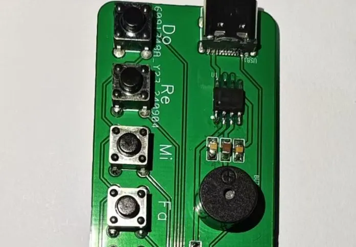
NE555 chip x1,
Resistors (various resistance values)
, Capacitors (various capacitance values)
, Buzzer or Speaker,
Key
Circuit Design,
NE555 Chip Configuration
: Configure the NE555 chip to oscillator mode (also known as square wave generator mode).
Connect the power supply to pin 8 (VCC) and pin 1 (GND) of the NE555 chip.
To set the oscillation frequency,
connect a capacitor (C1) between pins 6 and 2 of the NE555; this determines the oscillation frequency.
The pitch can be adjusted by changing the resistors (R1) between pin 7 (discharge pin) and pin 6, and (R2) between pin 6 and pin 2. A potentiometer can be used instead of a fixed resistor for pitch adjustment.
To output sound
, connect pin 3 (output pin) of the NE555 chip to the positive terminal of a buzzer or speaker.
Connect the negative terminal of the buzzer or speaker to ground (GND).
Experimental Procedure:
Connect the components of the NE555 chip according to the circuit diagram.
Adjust the resistance values using the buttons and observe the changes in the sound emitted by the buzzer to achieve different pitches.
Multiple such circuits can be designed, and different circuits can be switched using buttons to simulate a simple electronic keyboard.
Debugging and Improvement
: Adjusting the pitch: Different pitches can be obtained by adjusting different resistor values.
Sound Effects: Experiment with adding filters or modulation circuits to the buzzer or speaker to achieve richer sound effects.
Expanded Functionality: Add more buttons, each connected to a different NE555 circuit, to achieve multi-tone keyboard effects.
Summary:
Building a simple electronic keyboard using the NE555 chip is a fun and educational project. By adjusting resistors and capacitors, you can create various pitches and experience the joy of electronic music. This project also provides a good practical opportunity to learn and master basic electronic circuit design.


 京公网安备 11010802033920号

 M38226MBHFS


