Foreword:
This design is for tinkering, learning, and technical exchange only.
No guarantees are made regarding the final effect.
Production use is not recommended.
The author will not be responsible for any losses incurred.
It is not recommended to build without a VNA, although this may not be necessary in practice.
Chip inconsistency may be poor, and your final result may differ.
Regarding the antenna, since the manufacturer does not provide more information (and is unlikely to), the array effect is entirely based on guesswork and mental testing. Of course, my own testing has shown some effect, but there are no guarantees.
The antenna is a religious subject; I respect and tolerate your beliefs, and I hope you can accept that others are different from you. Thank you.
The wiring is a random drawing; please be gentle.
Open source license: CC BY-NC-SA 4.0 (NC = Non-Commercial).
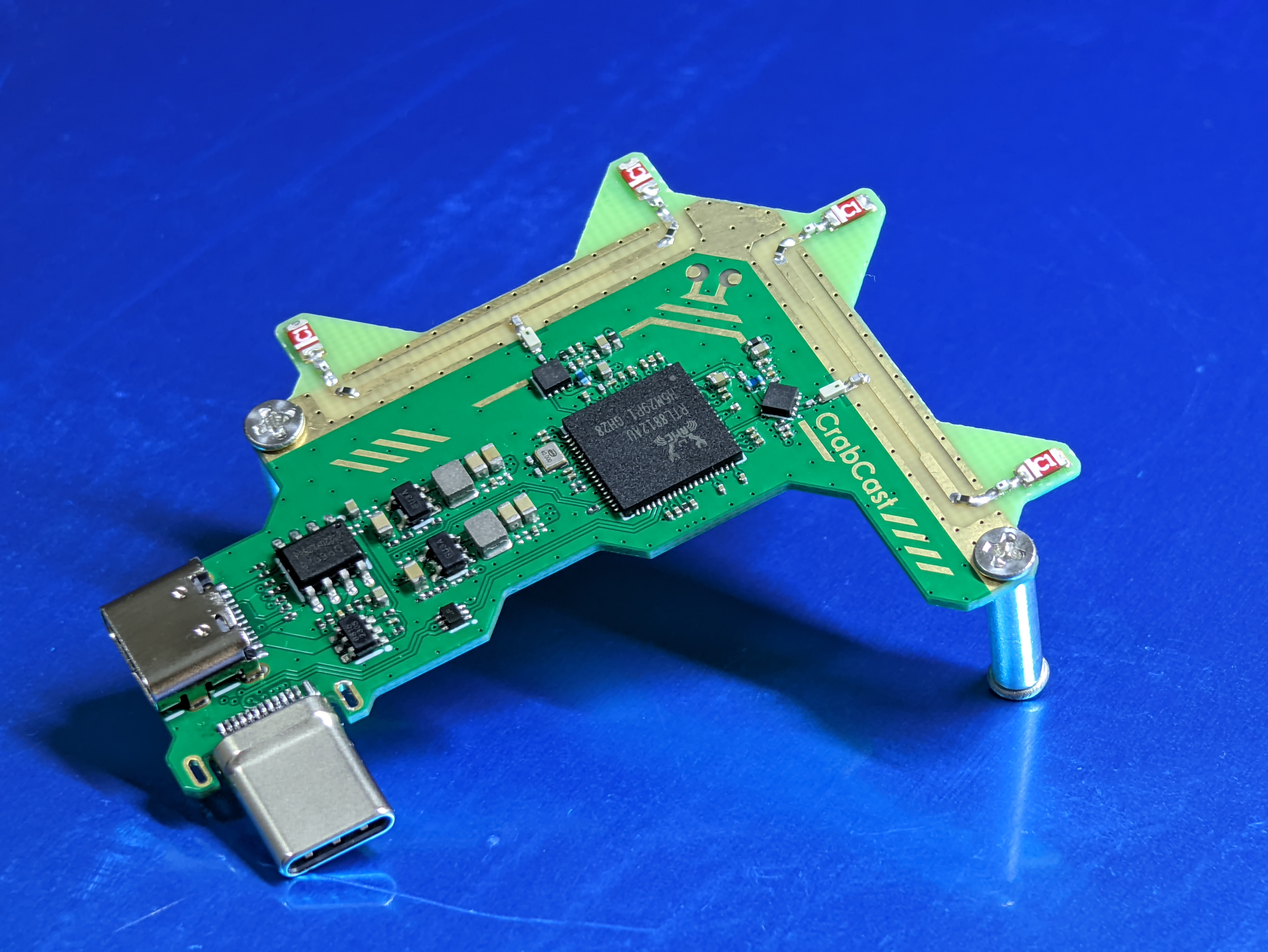
The crabs on the back are the actual Crab™ logo; please do not misuse this logo when replicating.
My board is purely a personal project for educational purposes and does not involve any commercial use. If it still infringes on your rights, please contact me to remove the silkscreen from the board.

What is this
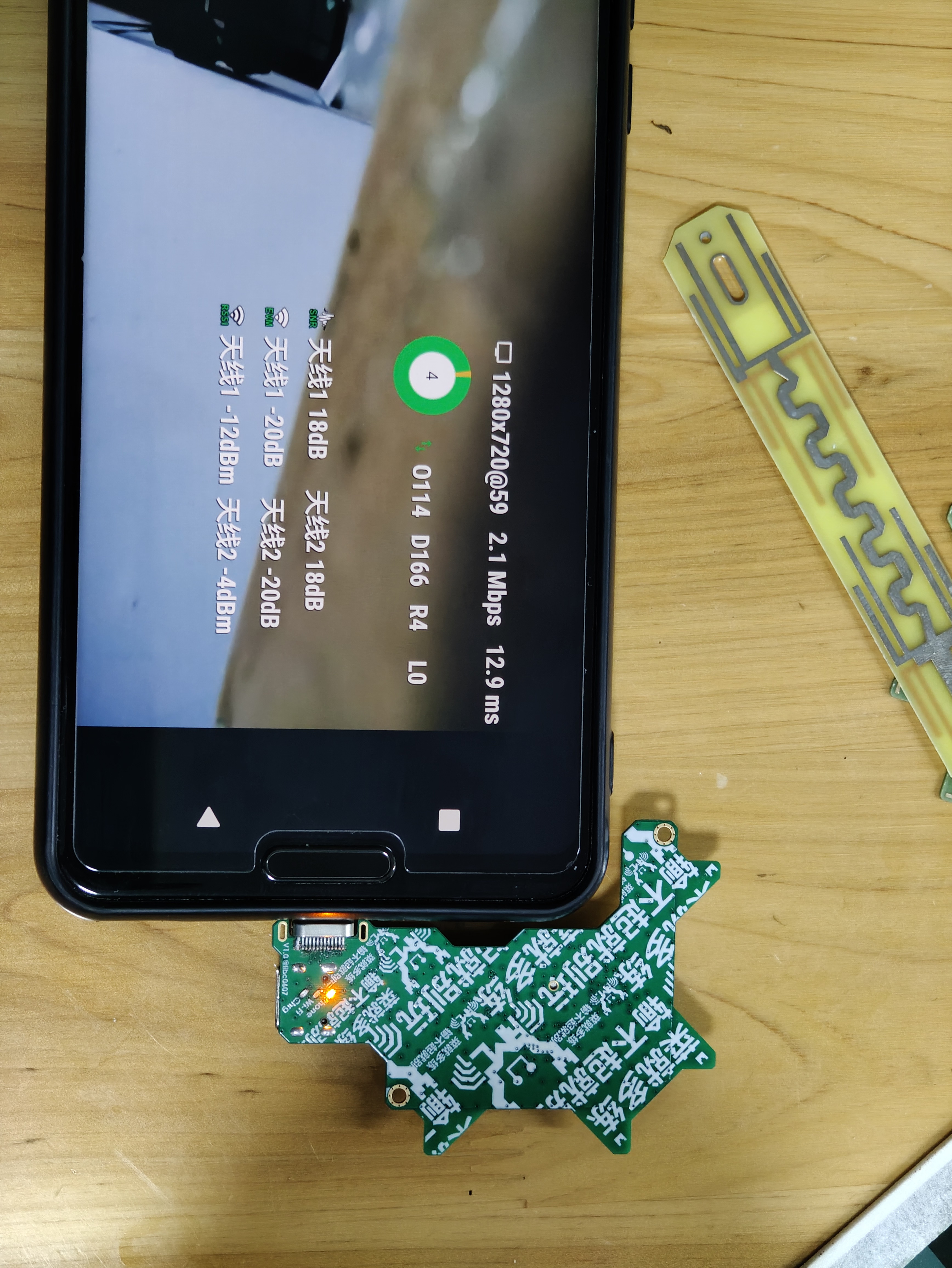
RTL8812AU pure receiver network card?
Its design goals are: 1. No external antenna required; 2. Small size, direct connection to a mobile phone without causing poor interface contact due to excessive weight; 3. Decent reception performance and slight directionality; 4. Can power the phone and also (slowly) charge it; 5. Cost should not be too high.
RF front-end: 5.15~5.85GHz bandpass filter (I used LCSC C2442150, for reference only, but it can be replaced) + QPL9503 LNA, 2 sets in total; does not support 2.4G band.
Antenna: OA-C01, 2 pieces per channel combined (4 pieces in total), two channels RX 90° placement, optional external reflector.
Data: Type-C male connector for direct connection. Power
supply: Another Type-C female port supports 5W input for simultaneous use and charging, with chip-based automatic PD role switching.
PCB/BOM
: JLC. 4-layer 7628 (the one you can get for free), 0.8mm total thickness, immersion gold, remember to select the 20% impedance option. Place the QR code in the designated position on the front, below the USB box. Order
components according to the component values in the schematic. You can order from LCSC Mall/Taobao. Some components can be replaced yourself depending on your understanding of the circuit. For
dual PMOS, you can choose a similar Rdson model, since this board only has 5V. If they are out of stock, you can find a model to replace it with
RTL8812AU. It's best to buy an efuse chip without data (brand new?). If it has data, it may affect the LNA enable control. If you unfortunately buy one with data, then refer to the software settings/driver modification/Realtek documentation for programming, etc.
I bought a used one from here. I bought an empty efuse chip for RTL8812AU from here in early September 2024. This is for reference only, and I make no guarantees.
All capacitors marked TBD in the schematic are the kind that... can be used without soldering, and soldering them on the power supply will make it cleaner... If you're soldering, I recommend soldering several capacitors of varying sizes that you have on hand. For
the Type-C male connector, you can apply two blobs of solder to the adjacent pads to increase strength.
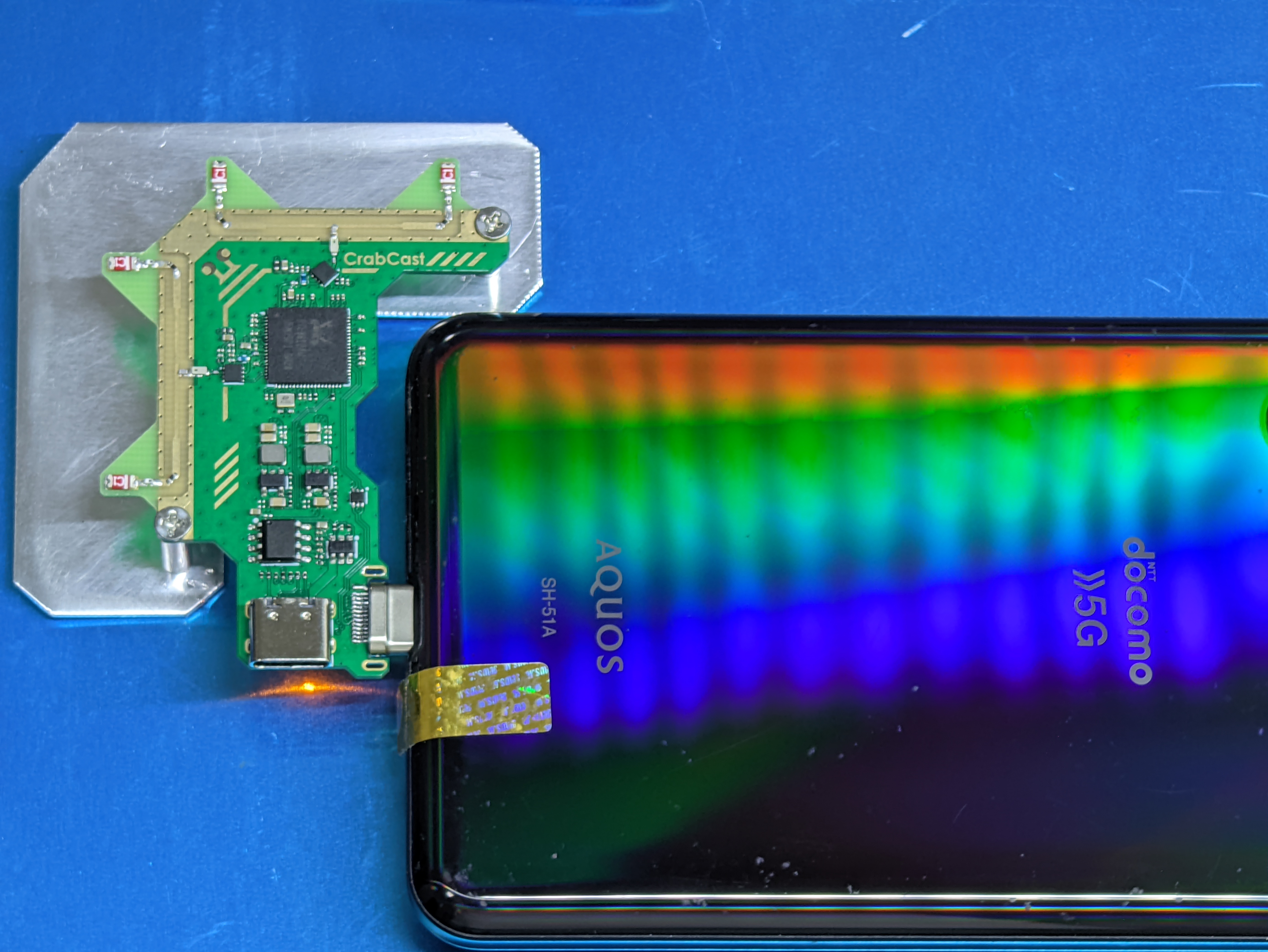
Besides the components shown in the schematic, if you need a reflector to slightly increase directivity, you'll need to buy some aluminum plates, cut and drill holes yourself, or draw a PCB of a suitable size with only copper plating, and fix it with M2 screws and studs (reference range: approximately 9mm~12mm, adjust according to actual conditions). See the image below;
the RTL8812AU generates considerable heat. You can

use it with a heatsink
. It's a receiver-only network card, so it can't be used as a regular Wi-Fi network card.
Compared to a standard RTL8812AU network card, since efuse is likely empty, you may need to modify some parameters to make the driver work correctly.
If you're wondering if efuse affects reception performance—currently, almost all parameters seem to only relate to transmit power. No obvious problems have been found in use yet; further observation is needed to determine the specific impact.
The definition of efuse can be found here.
Discussions about efuse are welcome. Taking
Linux
as an example (svpcom/rtl8812au), the process should be similar for others.
You need to add `rtw_amplifier_type_2g=0 rtw_amplifier_type_5g=192 rtw_RFE_type=4` to `insmod`.
The meanings of the parameters are as follows (see here):
`
rtw_amplifier_type_2g= "BIT3:2G ext-PA, BIT4:2G ext-LNA"` `rtw_amplifier_type_5g="BIT6:5G ext-PA, BIT7:5G ext-LNA"`
`ODM_BOARD_DEFAULT = 0, // The DEFAULT case.`
`ODM_BOARD_MINICARD = BIT (0), // 0 = non-mini card, 1= mini card.`
`ODM_BOARD_SLIM = BIT (1), // 0 = non-slim card, 1 = slim card` `
ODM_BOARD_BT = BIT (2), // 0 =` without BT card, 1 = with BT
ODM_BOARD_EXT_PA = BIT (3), // 0 = no 2G ext-PA, 1 = existing 2G ext-PA
ODM_BOARD_EXT_LNA = BIT (4), // 0 = no 2G ext-LNA, 1 = existing 2G ext-LNA
ODM_BOARD_EXT_TRSW = BIT (5), // 0 = no ext-TRSW, 1 = existing ext-TRSW
ODM_BOARD_EXT_PA_5G = BIT (6), // 0 = no 5G ext-PA, 1 = existing 5G ext-PA
ODM_BOARD_EXT_LNA_5G= BIT (7), // 0 = no 5G ext-LNA, 1 = existing 5G ext-LNA
rtw_RFE_type =
01h: RFE is used "SW_LNA_PA, ex SKY85703" for APA_ALNA board type.
02h: RFE is used "SW_LNA, ex. SKY85601" for ALNA board type. (When efuse
0xCA[7]=1, the board type is ALNA)
03h: RFE is used "2G&5G SW+PA+LNA", for PA_LNA board type. (When efuse
0xCA[7]=1, the board type is PA_LNA)
04h: RFE is used "SP3T" for DEFAULT board type.
Since this schematic is based on the SP3T reference design, and the switching logic is also based on that design, setting rtw_RFE_type to 4 here
will most likely result in 2 for the disassembled chip, which may cause the LNA to be unable to be enabled correctly. If you insist on using a disassembled chip... you can test which polarity of TRSW and TRSWB is correct, and then modify the schematic. Then you can use the monitor mode to receive packets normally. The new
version of DigitalFPV
should be able to directly use an empty efuse chip; just solder the board, plug it in, and it will work.
(DigitalFPV technical exchange group 904031209
is a technical exchange group, not an OPENIPC after-sales group! Manufacturer after-sales issues will be kicked out!)
Software
based on the devourer user space driver, such as PixelPilot (FPVue) on Android / fpv4win on Windows,
may need to modify the devourer driver as needed.
One method is to modify the RFE type recognition logic of EepromManager::Hal_ReadRFEType_8812A(), so that when the RFE Option in the efuse is read as 0xFF (empty), a correct default value is used.
Another method is to use phy_SetRFEReg8812() to set the correct mode.


 京公网安备 11010802033920号

 TCA4029050AC015000-12.75M


