The charging module
uses the TP4056 chip for battery management, offering the following advantages: • Programmable charging current up to 1000mA • No MOSFET, sense resistor, or isolation diode required • Complete linear charger for single-cell lithium-ion batteries in an SOP package • Constant current/constant voltage operation with thermal regulation to maximize charging rate without overheating • 4.2V preset charging voltage accuracy up to ±1.5% • Charging current monitor output for battery level detection • Automatic recharging • Dual outputs for charging status, including no-battery and fault status indicators • C/10 charging termination • 55uA supply current in standby mode • 2.9V trickle charging device version • Soft-start limits inrush current • Battery temperature monitoring • 8-pin SOP-PP package. The charging current can be adjusted by changing the resistor R13 in the above schematic diagram.
II. Automatic switching circuit between external USB power supply and internal lithium battery power supply
: When no USB power supply is plugged in, the internal lithium battery is used for power.
When a USB power supply is plugged in, it switches to external USB power supply and charges the lithium battery.
1. The final power supply to the system is VCC.
2. Single battery power supply: When no USB is plugged in, the gate (G) of the P-channel MOSFET remains low due to the pull-down resistor. At this time, the MOSFET is turned on, and the battery's VBAT goes through the MOSFET to the switch and then to VCC.
3. Single USB power supply: When no battery is plugged in, the gate (G) of the MOSFET is high after plugging in the USB, the MOSFET is turned off, and VUSB goes through the diode to the switch and then to VCC.
4. Battery and USB connected simultaneously: When VUSB is high, the battery does not supply power to the system through the MOSFET. This is the same as the single USB connection method, but due to the battery connection, the charging section starts working, and the USB simultaneously charges the battery.
III. The joystick
uses an ADC for data acquisition: The joystick is a bidirectional cross 10K resistor. The module uses a 5V power supply. In its original state, the X and Y axis voltages are approximately 2.5V. When the joystick is pushed in a certain direction, the corresponding axis voltage increases or decreases, with a maximum value of 5V and a minimum value of 0V. 1. Operating voltage: 5V 2. Output voltage range: 0~5V 3. Interface: Two analog signals represent X and Y offsets, and one digital signal SW represents whether the Z axis is pressed. For buttons, a standard I/O port is used to detect high and low levels to determine if the button is pressed. An external
WiFi
module can be connected, configuring the handshake protocol. An external Bluetooth module can also be connected.
(3D preview image,
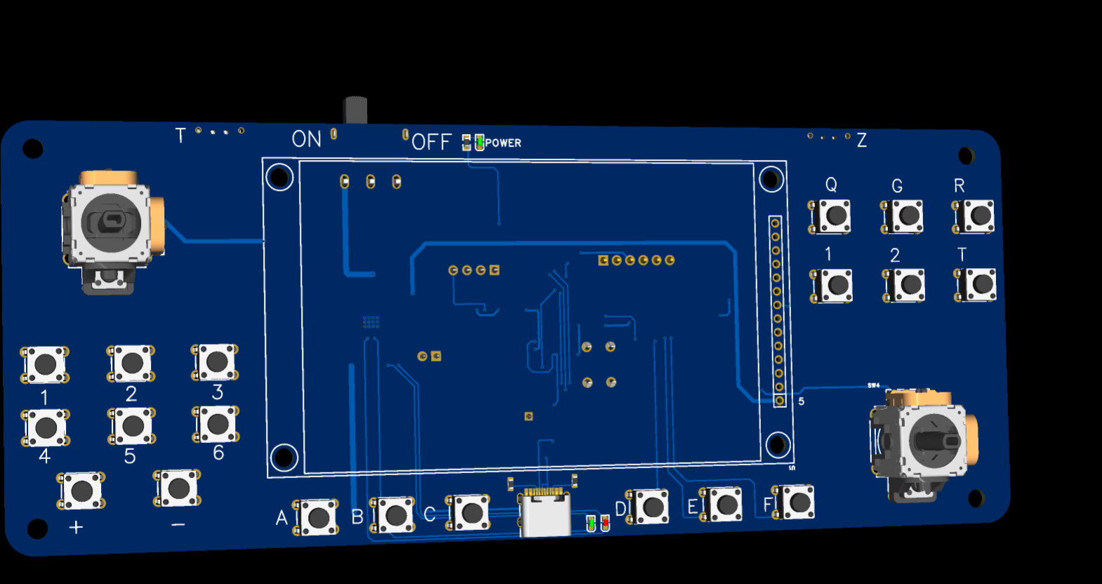
actual product image)

PDF_A--Handle.zip
Altium_A--handle.zip
PADS_A--Handle.zip
BOM_A--handle.xlsx
92116
ZHAO-Watch, a multi-functional oscilloscope watch based on STM32
An ordinary thing
This oscilloscope-based smartwatch, built with an STM32C8T6,
features:
》Basic time viewing and adjustment
》Smooth menu animation
》Super bright flashlight

》0~30V voltage measurement, resistance voltage divider

》200kHz sampling rate oscilloscope with input impedance
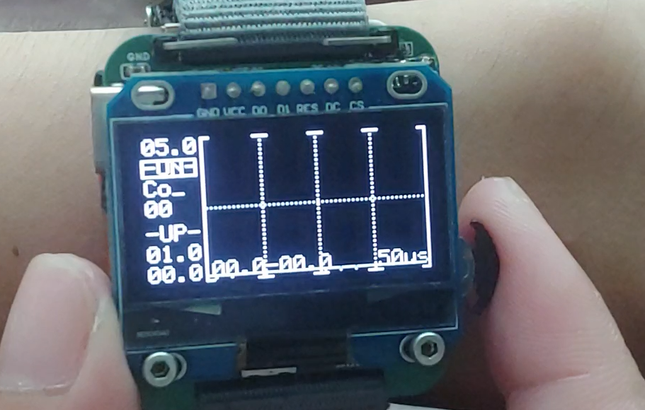
》Equipped with a FarT2 wireless module, capable of controlling 315MHz or 433MHz devices
》A Conway game of life
》A calculator capable of continuous calculations, including four arithmetic operations, square roots, trigonometric functions, and inverse trigonometric functions
》Equipped with a SU-21T low-power voice recognition module, supporting 50 commands, and can be combined with other functions on the watch for voice control
》Wrist-raise wake-up (implemented with MPU6050, relatively high power consumption)
》Can connect to a computer to directly copy reply words.
See the Bilibili demo video for details:
https://www.bilibili.com/video/BV1ob4deyEc6/
An attachment contains a boot animation demo that I personally find very cool (it only appears when the battery is powered on).
The boot animation program is hidden and cannot be seen in Keil. (づ ̄3 ̄)づ
Boot animation.mp4
ZHAO-Watch.zip
PDF_ZHAO-Watch, a multi-functional oscilloscope watch based on STM32.zip
Altium-based STM32 multi-functional oscilloscope watch ZHAO-Watch.zip
PADS_ZHAO-Watch, a multi-functional oscilloscope watch based on STM32.zip
BOM_ZHAO-Watch, a multi-functional oscilloscope watch based on STM32.xlsx
92118
ESP32 Drying Oven
ESP32 drying oven, DHT11+18B20 temperature sensor, serial port display – let's test the situation.
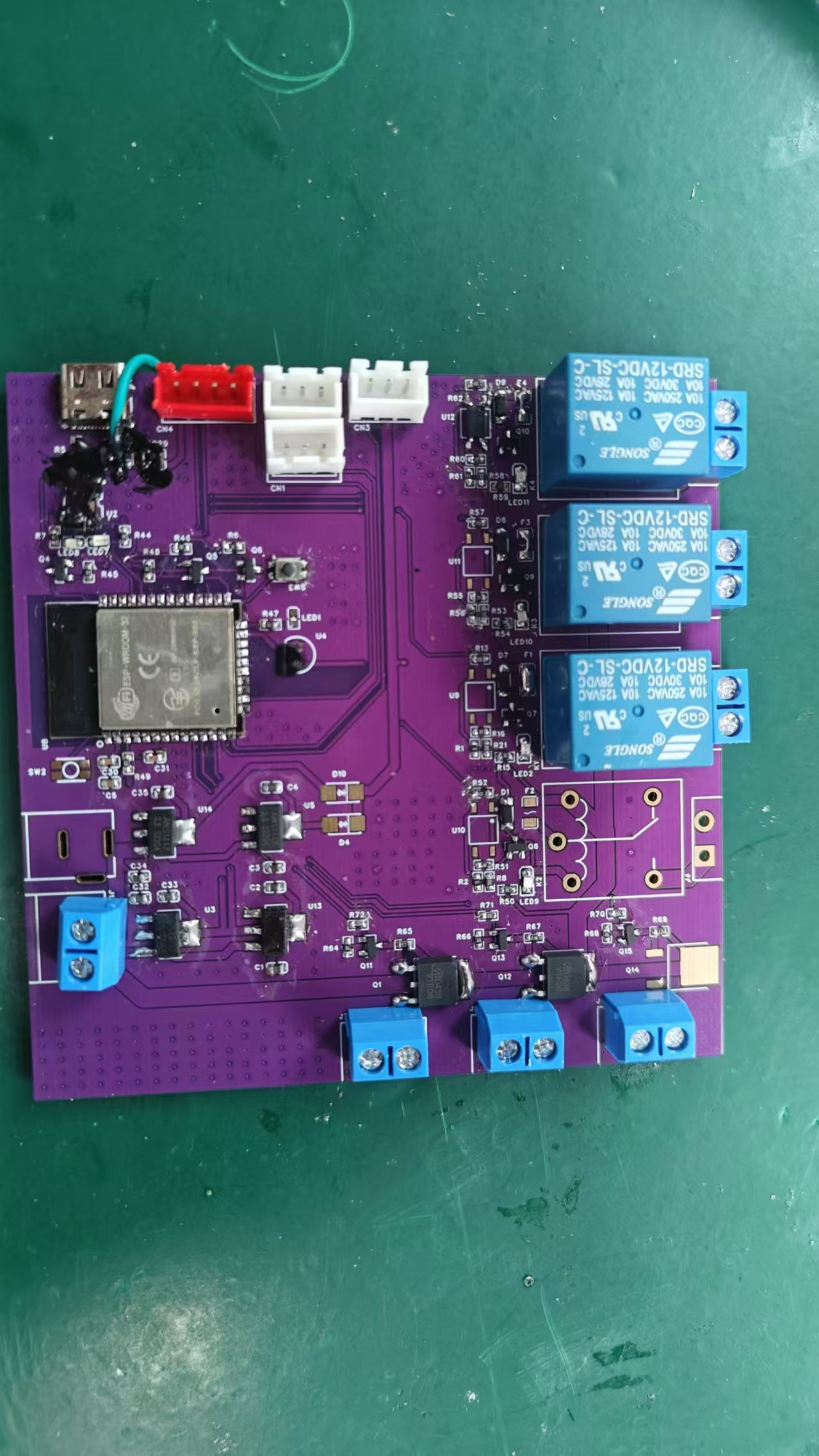
The ESP32 drying oven
uses the ESP32-WROOM-32-N4 main controller, which has three 18B20 temperature probes and one DHT11 sensor.

CN1 is a DHT11
, CN2 and CN3 are 18B20, and
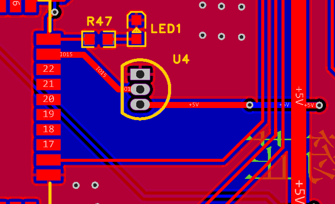
u4 is an 18B20 plug-in. It can simultaneously collect temperature data from four locations and adjust the temperature via four heating elements. The number of heating elements connected depends on the size of the drying oven.
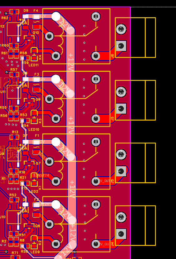
Relays connect to the heating elements. The power supply is 12V, and the maximum current of a single fuse is 2A. The maximum power of a single heating element is 24W; currently, 18W is used.
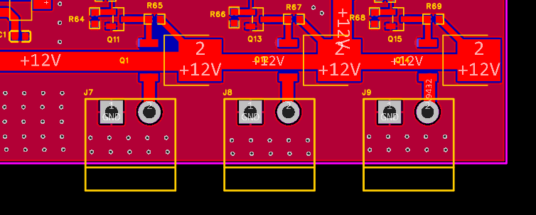
This is the fan control terminal, which adjusts the fan speed to ensure stable internal circulation.
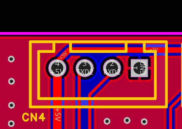
CN4 is a serial port display, showing the internal status in real time .
A picture of the actual product is shown below.
ed8dbd866dce40394454632226e7f5c5.mp4
PDF_ESP32 Drying Oven.zip
Altium_ESP32 Drying Oven.zip
PADS_ESP32 Drying Oven.zip
BOM_ESP32 Drying Oven.xlsx
92119
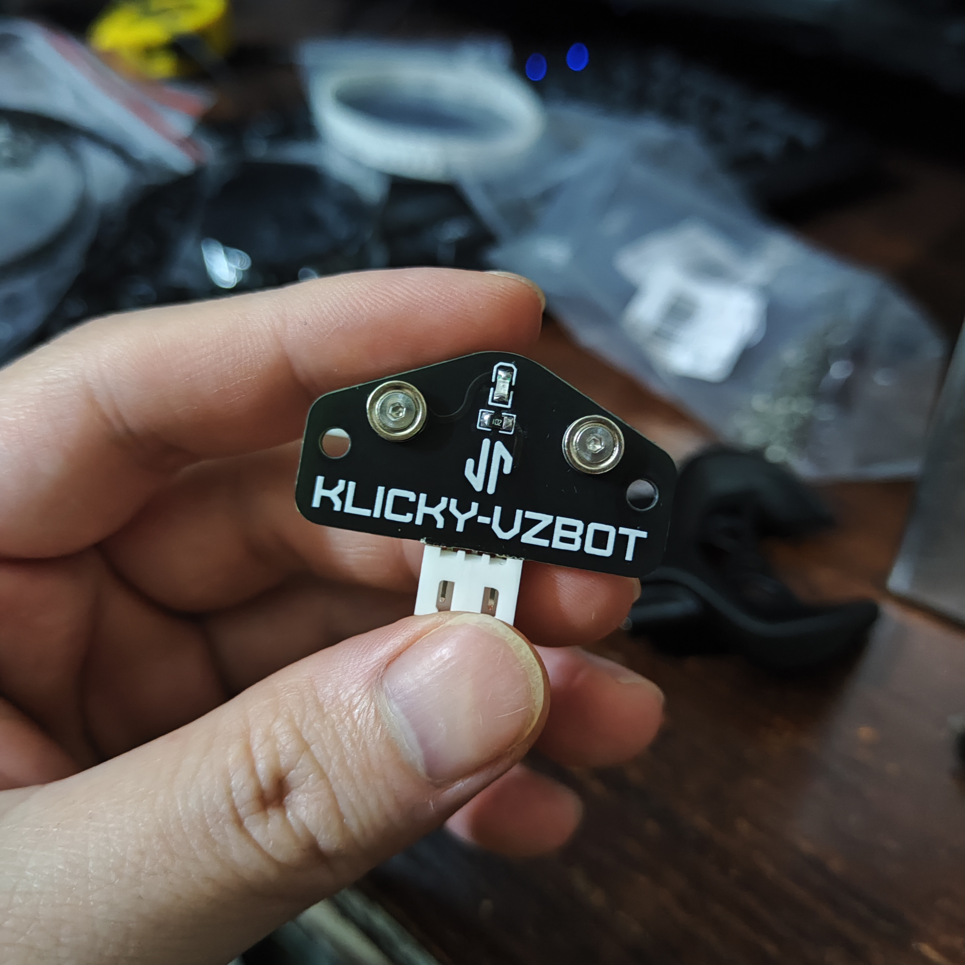
vzbot klicky beacon version
Compatible with VZBot Gloria
, compact, stable, and high-precision.
Awesome! Stable!! VZ...Boom!!!
Mom no longer has to worry about my VZbot not being leveled!
Assembly:
https://www.bilibili.com/video/BV1j6421w7qQ/?share_source=copy_web&vd_source=684b9369c5f1a47552ffbf5cceab4d0c
Testing:
https://www.bilibili.com/video/BV1NJ4m1873m/?share_source=copy_web&vd_source=684b9369c5f1a47552ffbf5cceab4d0c
*Plate thickness 1.6mm
Material
quantity
requirements and uses
Outer diameter 6*thickness 2-hole M2 countersunk strong magnet
2
countersunk adsorption, for upper plate
https://m.tb.cn/h.5xdFq6ItlSIPAE6?tk=HRJCWMmJ1By
Outer diameter 6*thickness 3-hole M2 countersunk strong magnet
2
countersunk adsorption, for lower plate
https://m.tb.cn/h.5Chli0fY73ATZeI?tk=xMZ5WMmJ1eD
M2X₵5.5X1+₵3.6X1.5 SMD nut
4
Countersunk hexagon M2*5 Suitable for 1.27mm wrench
4
Flat
head hexagon M3x4
2
XH2.5 4 Port straight pin 3P
1
Attached air duct printout
1
This air duct has been modified to better fit Klicky
micro switch
1
0805 resistor 1K
1
0805 LED
The upper
plate uses a 6mm outer diameter, 2mm thick M2 countersunk magnet;
the lower plate uses a 6mm outer diameter, 3mm thick M2 countersunk magnet.

Assembly effect:
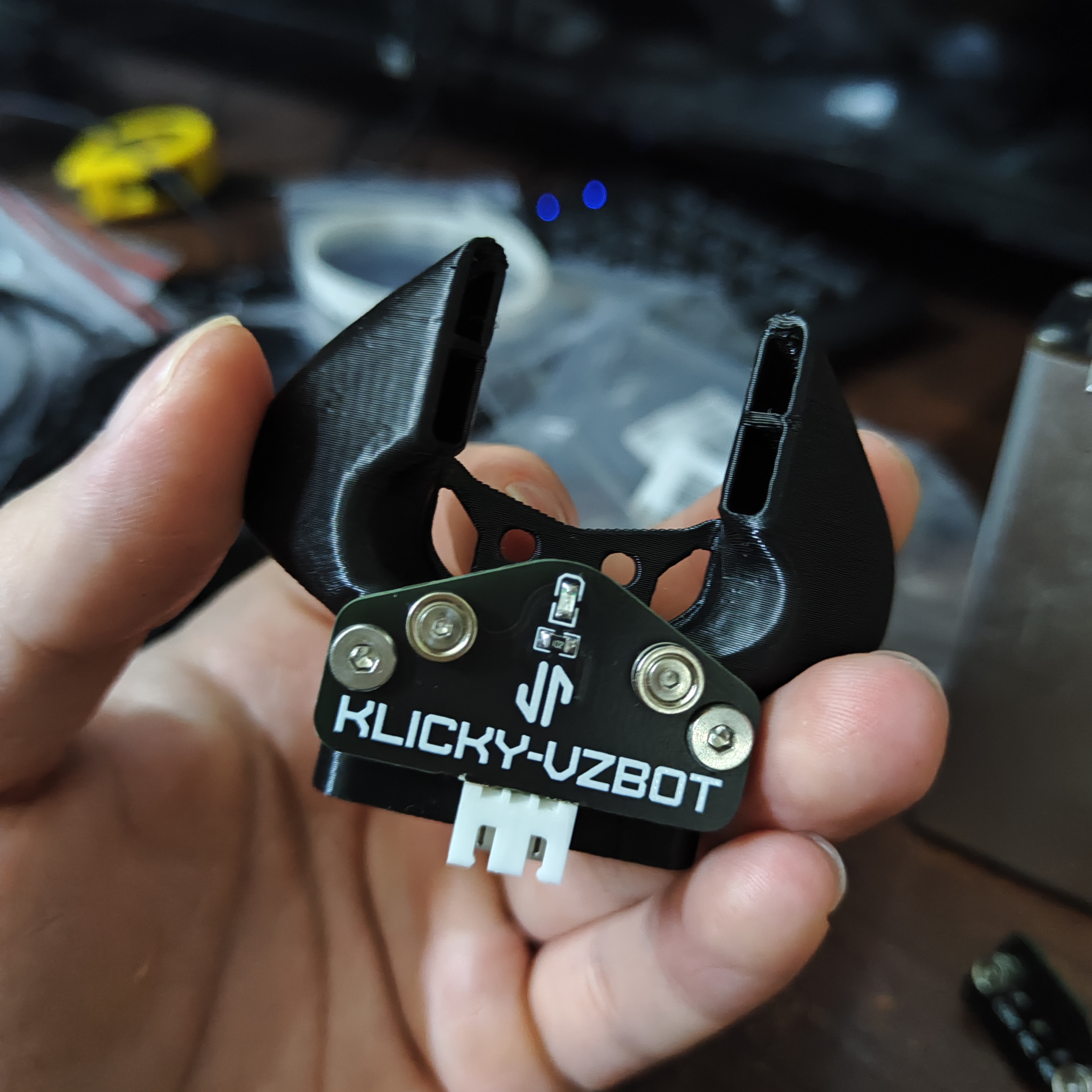
docking dock.

Goliath short klicly - air duct. stl
docking height adjustment.step
Dock.step
PDF_vzbot klicky beacon version.zip
Altium_vzbot klicky beacon version.zip
PADS_vzbot klicky beacon version.zip
BOM_vzbot klicky beacon version.xlsx
92121
A 7-port USB hub design based on FE2.1 (verified)
A 7-port USB hub design based on FE2.1 (with independent power supply)
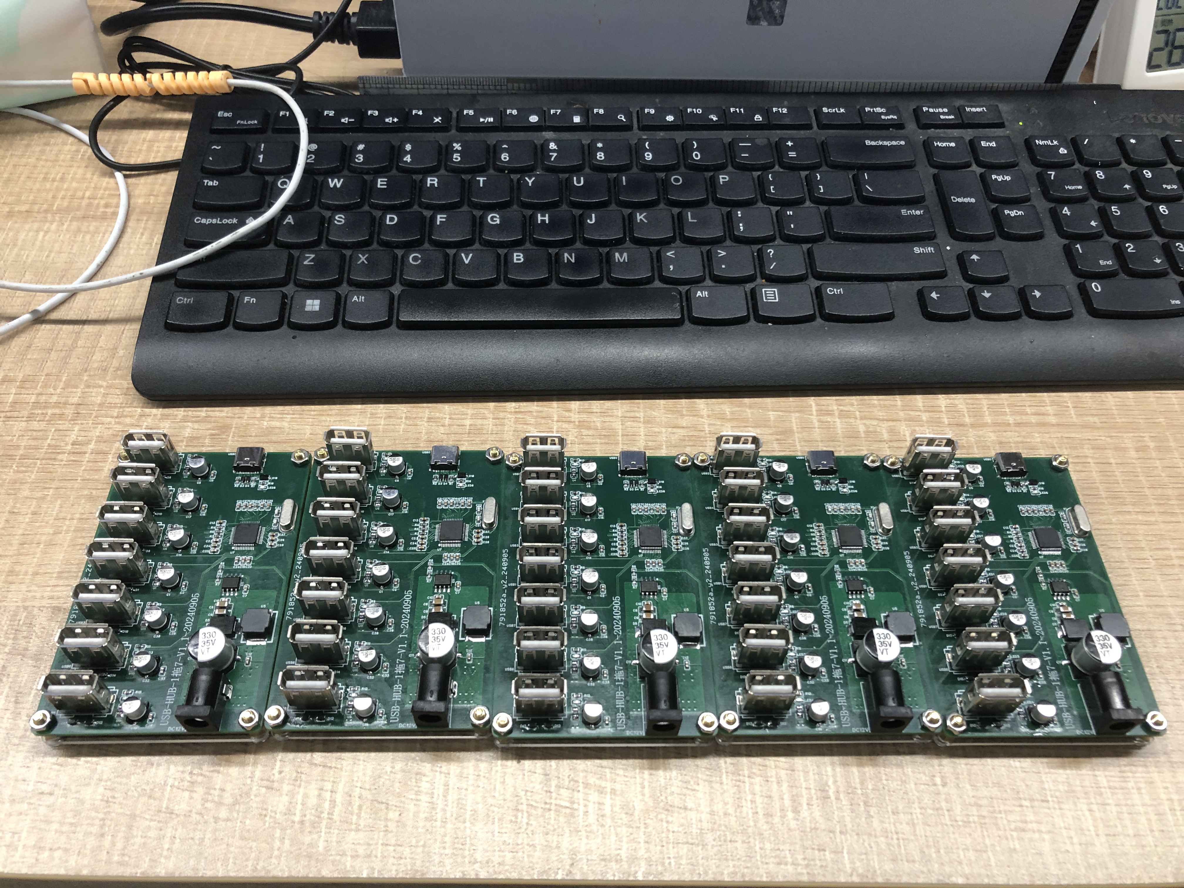
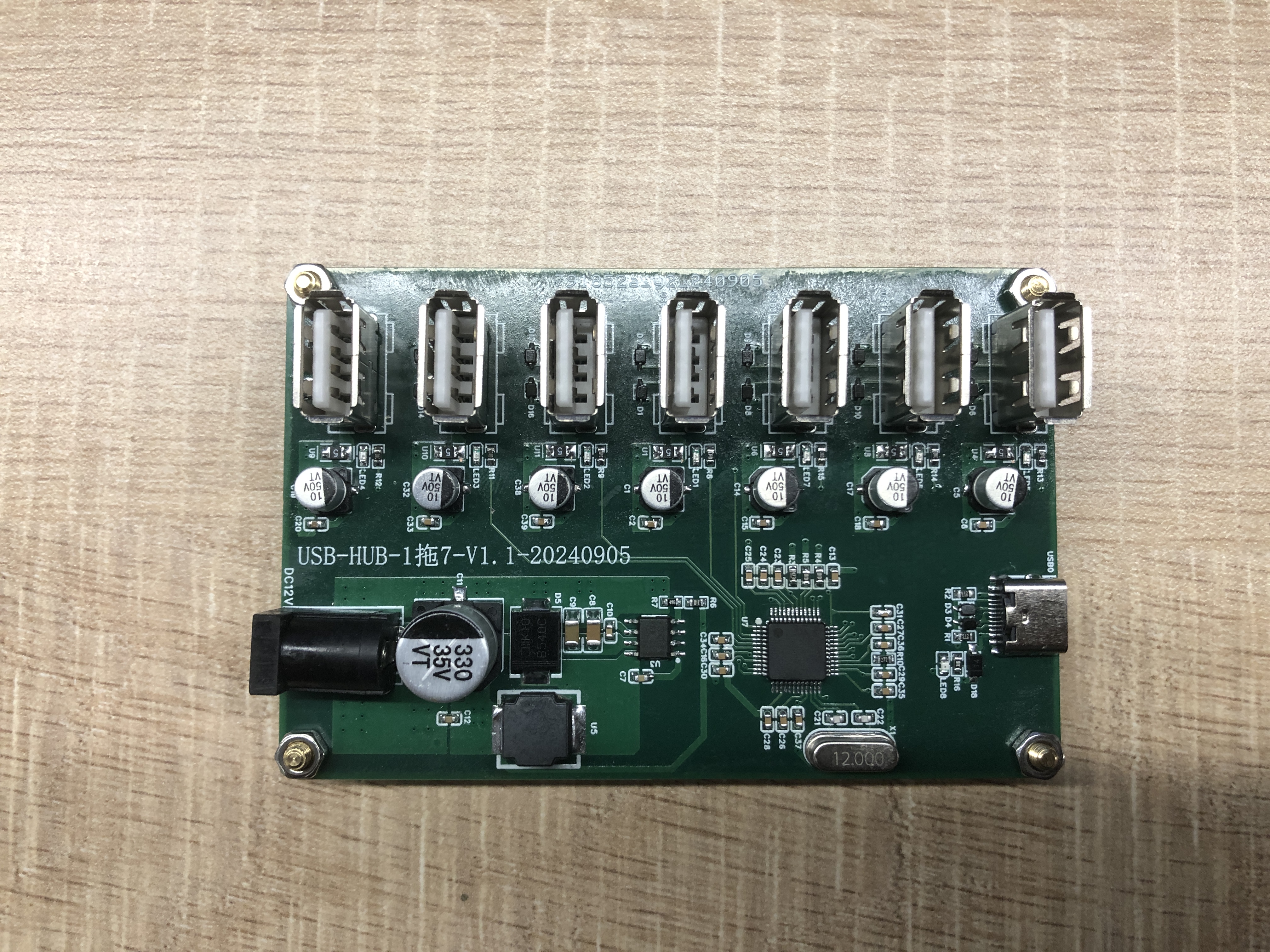
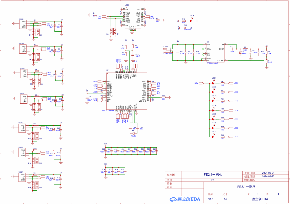
To address the issue of insufficient USB ports, a 7-port USB hub based on the FE2.1 chip was designed. It uses a Type-C input port to connect to the computer, while the other seven are standard USB 2.0 ports.
This is the second version, adding independent power supply to the first. After prototyping the first version, it was found that it couldn't power devices with slightly higher power; at most, two USB ports would stop working. Therefore, a TPS5450 was used with a 12V adapter for power, with a maximum output of 5V/5A. This effectively avoids the problem of devices not being able to run.
This version has been verified to be working correctly and can be safely replicated.
![4fc0e6cdeb0425e9abbba2289810edb.jpg]
![f5c26e08e6280ca54080a8165166200.jpg]
![image.png]
Demo.mp4
SCH_FE2.1 One-to-Seven_2024-09-19.pdf
PDF_FE2.1-based 7-to-1 USB-HUB Design (Verified).zip
Altium_FE2.1-based 7-to-1 USB-HUB Design (Verified).zip
PADS_FE2.1-based 7-to-1 USB-HUB Design (Verified).zip
BOM_FE2.1-based 7-port USB-HUB Design (Verified).xlsx
92122
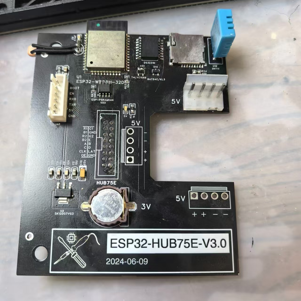
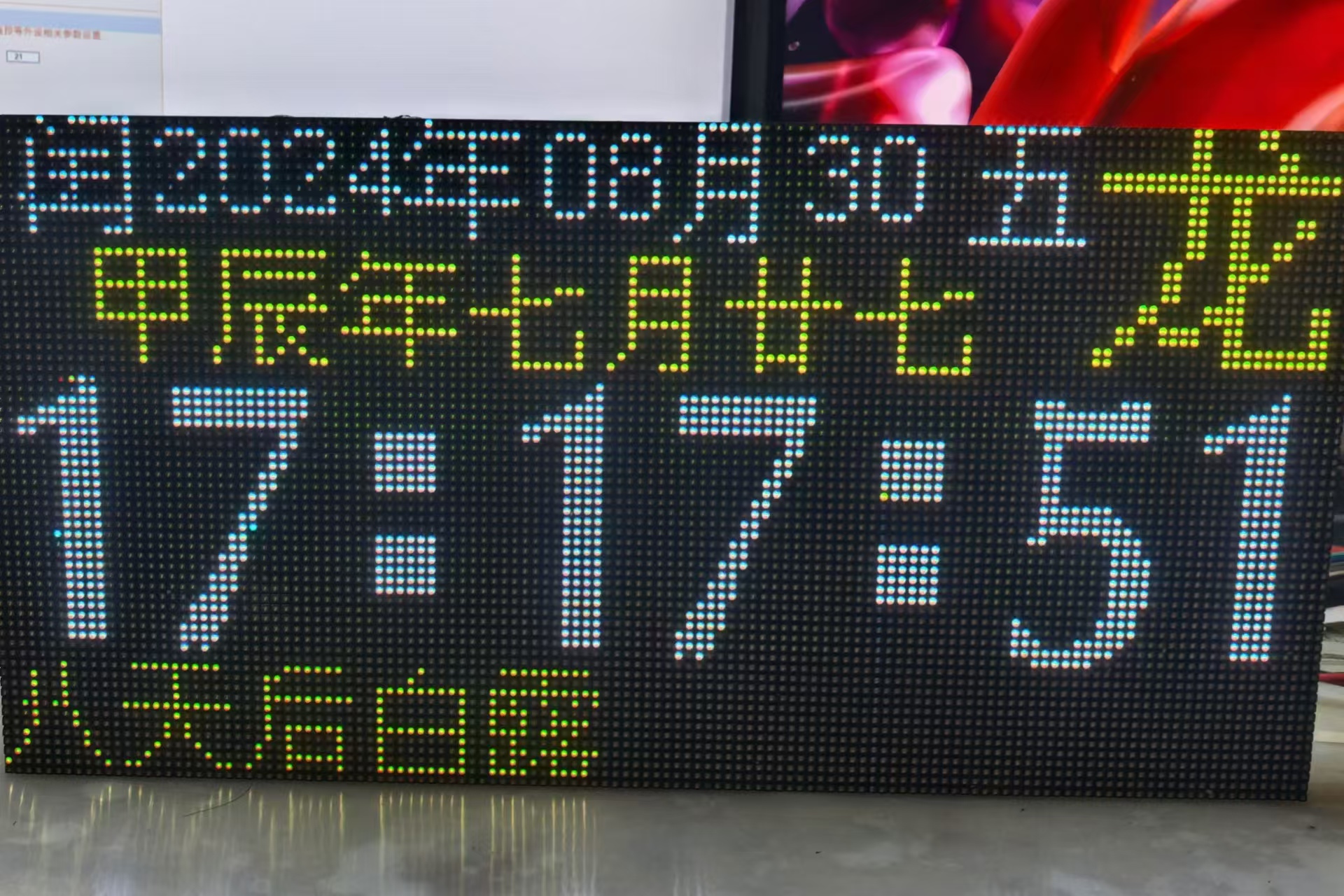
ESP32 HUB75E Controller
The HUB75 LED panel controller, designed using an ESP32 module, integrates a DS3231 clock chip, DHT11, TF card, and photoresistor detection.
This document
describes the design of the ESP32-S3 HUB75E controller
, a HUB75 LED panel controller designed using the ESP32 module.
It features 8MB of PSRAM for a richer interface, an integrated DS3231 clock chip, DHT11, TF card, and photoresistor detection. Notes: The HUB75E uses a 2.54-16P dual-row female connector, which needs to be soldered to the back.


WeChat_20240830171903.mp4
WeChat_20240830171912.mp4
RGB-LED Display HUB75e Interface Driver Board_V3.0.epro
PDF_ESP32 HUB75E controller.zip
Altium_ESP32 HUB75E controller.zip
PADS_ESP32 HUB75E controller.zip
BOM_ESP32 HUB75E controller.xlsx
92123
electronic


 京公网安备 11010802033920号

 82C288-10


