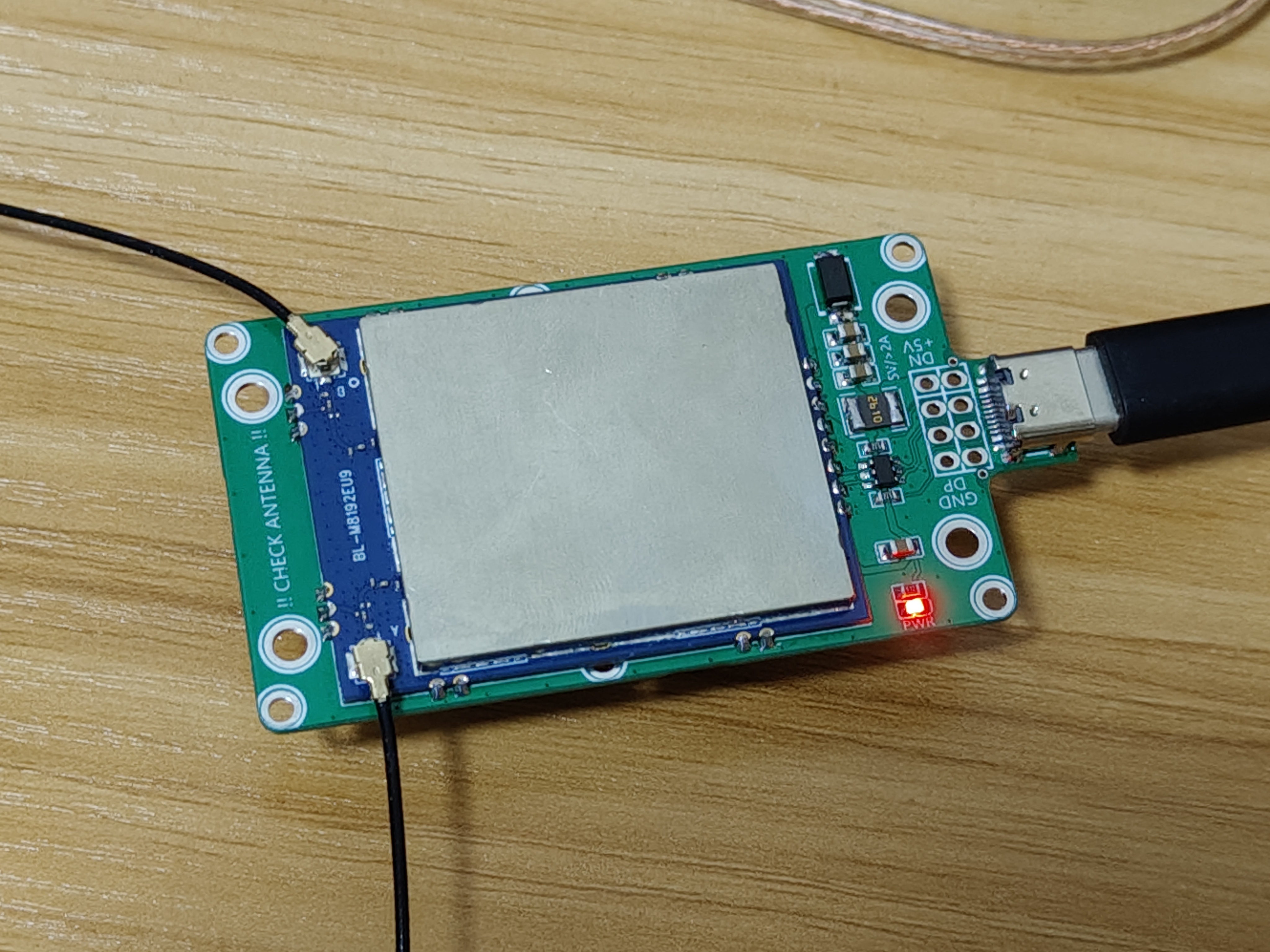
The BL-M8192EU9 verification board
is not usable in the domestic 915 frequency band, which makes it difficult to implement image transmission in the 2.4G frequency band. But since the design is already done, and it's usable—even as a regular network card (Windows driverless) with a surprisingly strong signal—I'll post it anyway…
The board is 0.8mm thick, with holes compatible with 38 modules (through holes can't be drilled, M2 nuts need to be soldered), and 65*30 Type
-C holes compatible with Raspberry Pi Zero (or other similar models, such as some Radxa RK development boards). The design is for easy breaking along the first row of holes.
If you're curious about its power—first, you can check the manual. Also, its FEM model is KCT8243HE.
Before judging the power level of a Wi-Fi module, due to the differences in modulation methods between digital and analog video transmission, you may need to understand at least the following concepts, including but not limited to: PAPR, P1db, and IP3.
If you still have unrealistic expectations about the power of digital video transmission after learning these concepts, here's a recommended software to help you improve your understanding and clear up any confusion! Click to download.
When using wireless transmission, please comply with the laws of your region.
Module purchase link: https://item.taobao.com/item.htm?id=704482488973.
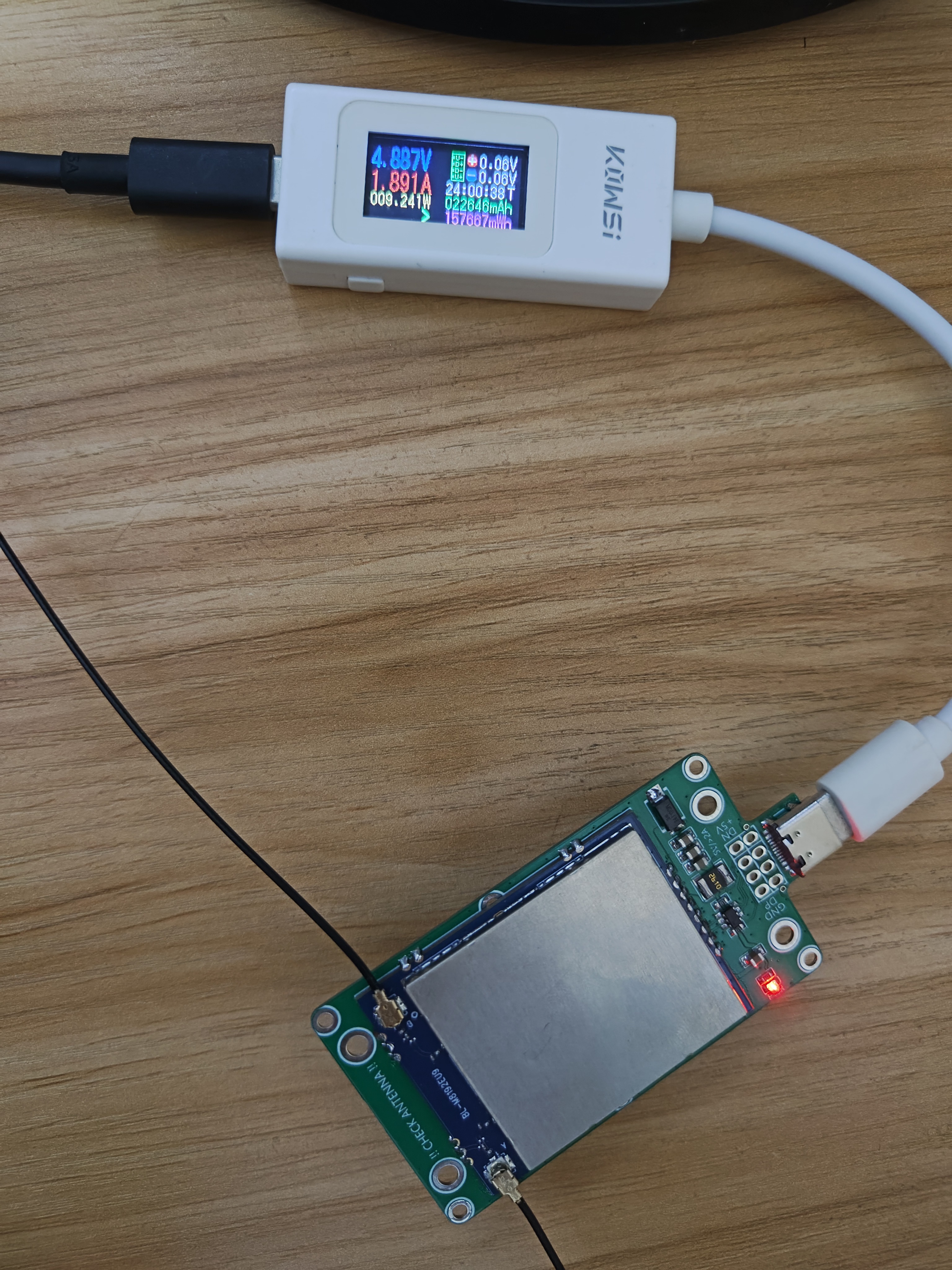
The injected packet current can reach over 1.5A, so heat dissipation is essential. The heatsink and fan on the back should be 25mm*25mm in size, with an XH2.54 connector and 5V voltage. For example, you can buy this: https://item.taobao.com/item.htm?id=600728482081.
Then, use thermally conductive double-sided tape to attach
the manual: https://github.com/libc0607/rtl8192eu-20220929/blob/main/doc/BL-M8192EU9_datasheet_V1.0.1.pdf
(original Linux). Driver package: https://github.com/libc0607/rtl8192eu-20220929/blob/50756de1c6fc38d7da060d29b9de56295bf995e0/doc/RTL8192EU_linux_v5.11.2.3-20-gbf6f4ca0d_COEX20171113-0047.20220929.tar.gz
My modified Linux driver supporting injection listening, usable with wfb-ng: https://github.com/libc0607/rtl8192eu-20220929
Waiting for someone to verify the OpenIPC firmware containing the above modified driver: https://github.com/libc0607/openipc-firmware

PDF_BL-M8192EU9 Verification Baseboard V1.0.zip
Altium_BL-M8192EU9 Verification Baseboard V1.0.zip
PADS_BL-M8192EU9 Verification Baseboard V1.0.zip
BOM_BL-M8192EU9 Verification Baseboard V1.0.xlsx
92357
Static electricity trap
electrostatic detector
This project involves the design and application of an electrostatic discharge (ESD) detector specifically designed to identify and distinguish between positive and negative static charges on object surfaces. The detector is equipped with blue and yellow wires; the blue wire detects positive charges, and the yellow wire detects negative charges. The device features high sensitivity, accurately identifying the electrostatic state of a target object within a 5-centimeter range.
This high-sensitivity design allows the ESD detector to detect static electricity accumulation in the environment or on object surfaces at close range (within 5 centimeters), responding quickly and effectively preventing potential risks such as spark discharges and damage to electronic components caused by static electricity. This equipment is widely used in static-sensitive environments such as electronics manufacturing, chemical production, and laboratory operations, providing necessary ESD protection, ensuring operational safety, and improving product quality.
PDF_Static Electrostatic Precipitator.zip
Altium_Static Electrostatic Extractor.zip
PADS_Static Electrostatic Extractor.zip
BOM_Static Electrostatic Discharge Device.xlsx
92358
Han Tianzun Theme Room
Inspired by Xin Ruyin's Inverted Five Elements Array and drawing inspiration from Han Tianzun's uncontrolled magical treasure in episode 62 of "A Record of a Mortal's Journey to Immortality," the theme scene (room) was created as a classic moment. Chips involved: STC15W104 main control chip, TP4057 charging management chip, and TTP233H touch chip.
Project Overview:
This project references a design by a netizen: https://oshwhub.com/IdeaMing/WS2812-STCkai-fa-ban, with buttons replaced by touch controls. It also draws inspiration from Warm Winter Creations - Light Painting: https://oshwhub.com/adlxy/warm-winter-lighting-painting. The panel is made of acrylic with a glossy line drawing and a colored backing; alternatively, you can refer to my article on making a panel using a colored PCB: https://oshwhub.com/article/color-screen-printing-light-transmission-verification.
An STC15W104 chip is used to control the switching of the WS2812 colored lights.
The project includes
Keil software, C language programming, a simple 8-pin STC15W104 (-351-SOP8) microcontroller as the main control chip;
control of 8 WS2812 chips (source code included, verified, and directly modifiable);
a TTP233H touch chip to replace the button switch;
a 3.7V to 3.3V converter (unsure if direct 3.7V lithium battery power is possible, reducing one chip); and
a lithium battery rechargeable module.
Areas for improvement include:
1. The 3D casing is too deep, making the lights too far from the panel and insufficiently bright;
2. Only 8 lights are used, all close to the lower half (they should be evenly distributed across the entire panel);
3. The switch only has two positions: battery power and charging, without labeling. This can cause the switch to falsely charge when the battery is dead;
4. Videos and photos do not accurately capture the colors seen with the naked eye.
WS2812B.rar
petal_20240909_215213.mp4
PDF_Han Tianzun Theme Room.zip
Altium_Han Tianzun Theme Room.zip
PADS_Han Tianzun Theme Room.zip
92359
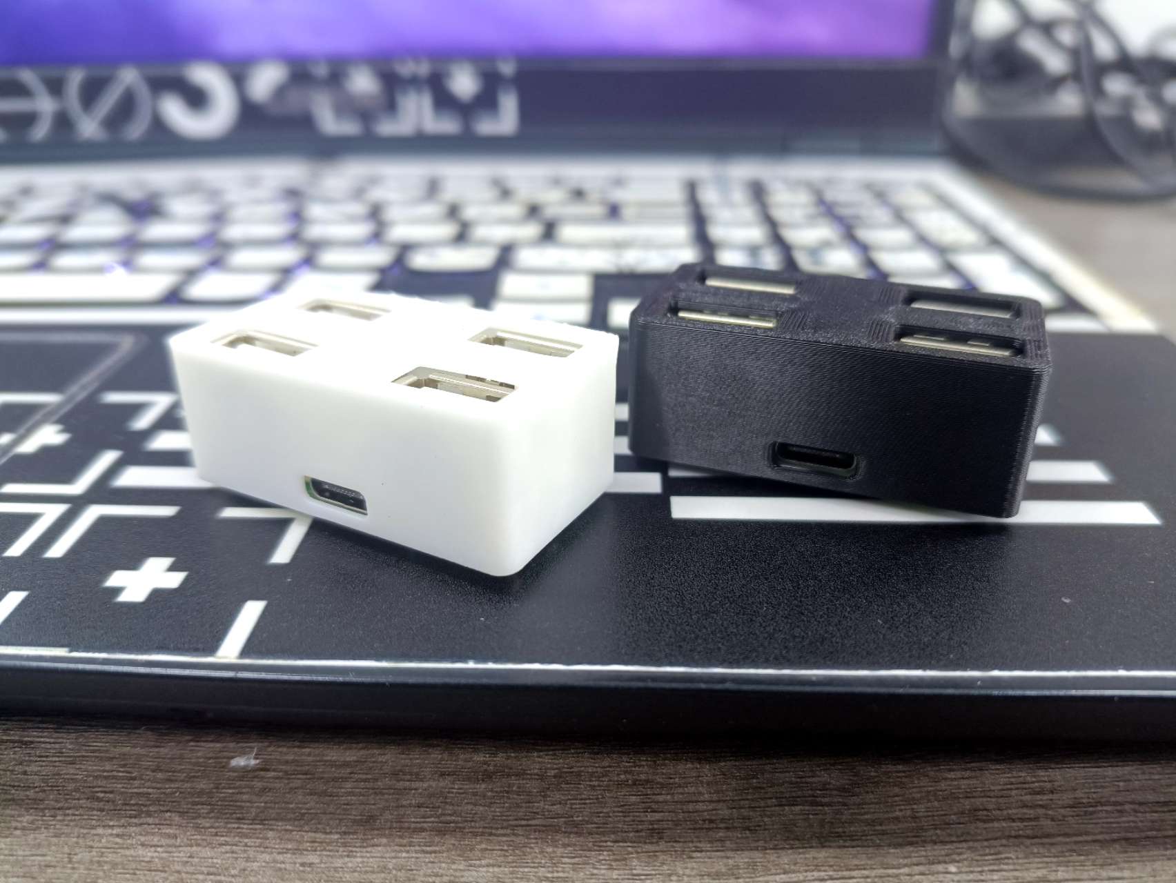
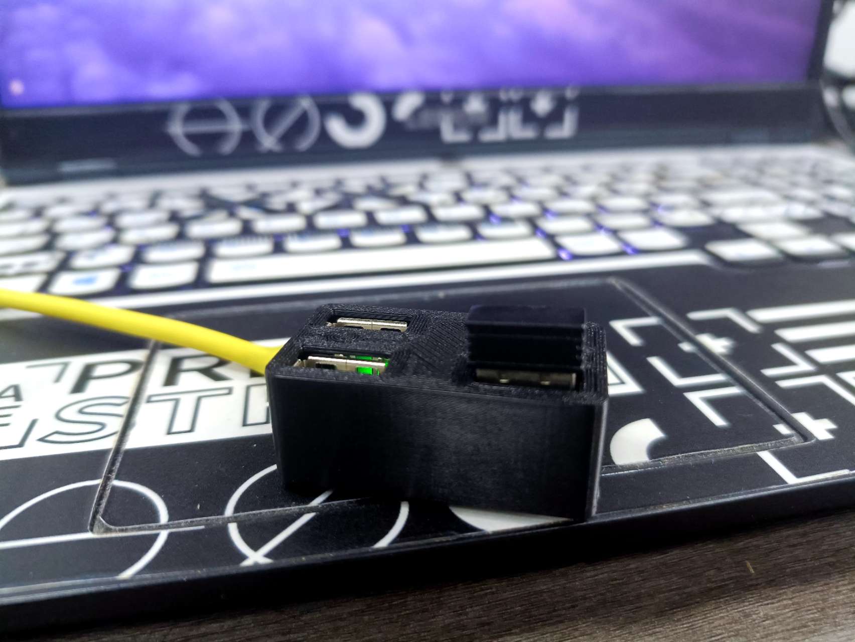
USB HUB - DIY USB Adapter Board
You can make your own USB hub that can convert one USB to four.
#01 Results

#02
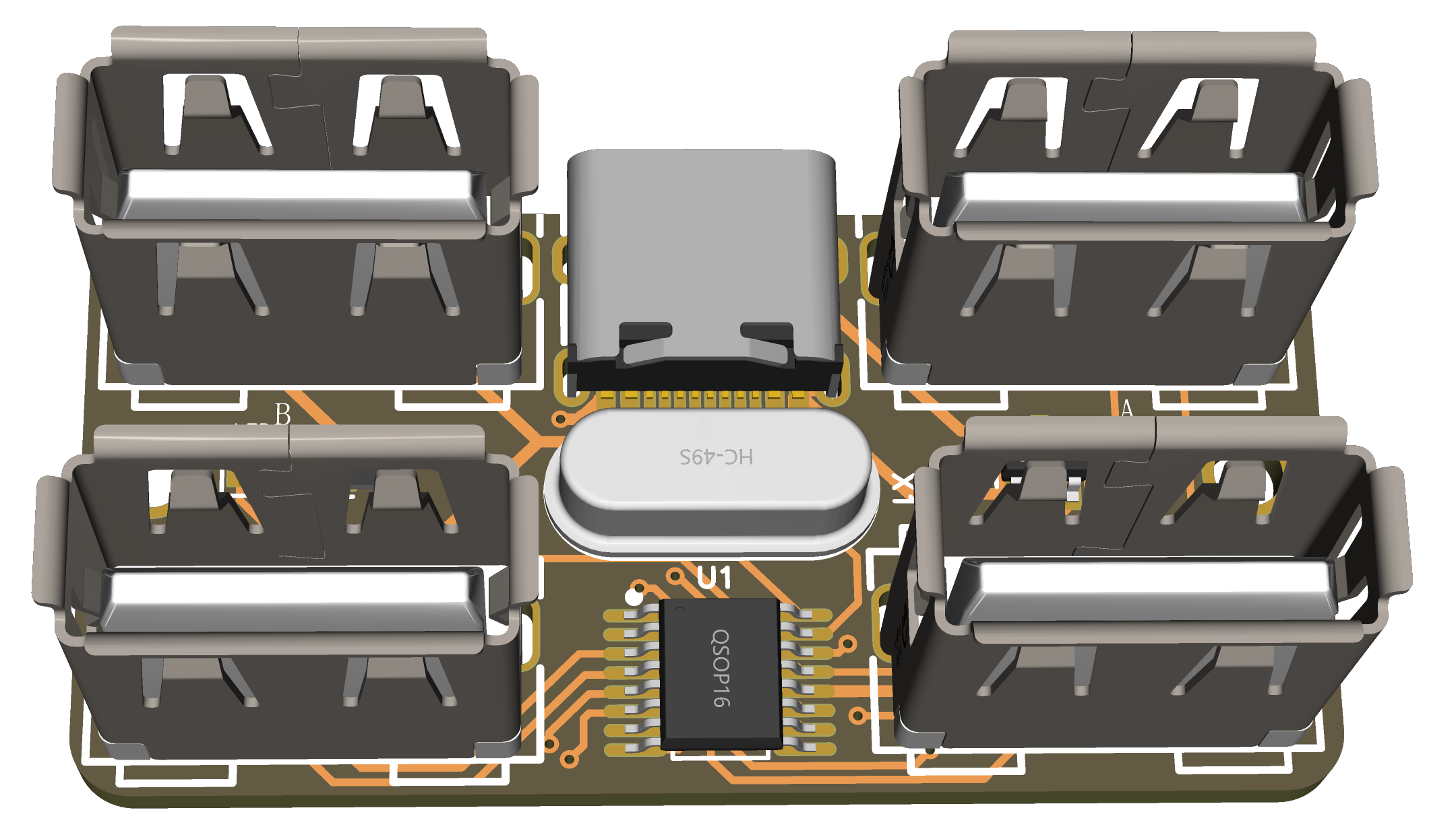
Project Use: A USB 2.0 expansion board was designed using the CH334R. The circuit design is relatively simple and the implementation cost is low, averaging around 10 RMB per board.
Because it's USB 2.0, it's suitable for connecting low-bandwidth devices such as mice and keyboards.
The project has completed circuit design, PCB layout, prototyping, and surface mount technology (SMT). A casing was also designed for the expansion board, which can be completed directly in LCSC EDA.
It has been successfully connected to a computer, and the mouse and keyboard have been tested without any issues.
Shell 3D file.zip
PDF_USB_HUB Homemade USB Adapter Board.zip
Altium_USB_HUB Homemade USB Adapter Board.zip
PADS_USB_HUB Homemade USB Adapter Board.zip
BOM_USB_HUB DIY USB Adapter Board.xlsx
92360
electronic


 京公网安备 11010802033920号

 R3111Q291B


