The AGM32VF103_QFP48 minimum development board contains a RISC-V CPU and FPGA 2K resources, offering high cost-effectiveness. Its pin-to-pin replacement for the STM32F103C8T6
has been verified as working correctly.
Desktop temperature and humidity ornaments, the 9th Training Camp of JLCIC—Desktop temperature and humidity ornaments, learn how to make them...
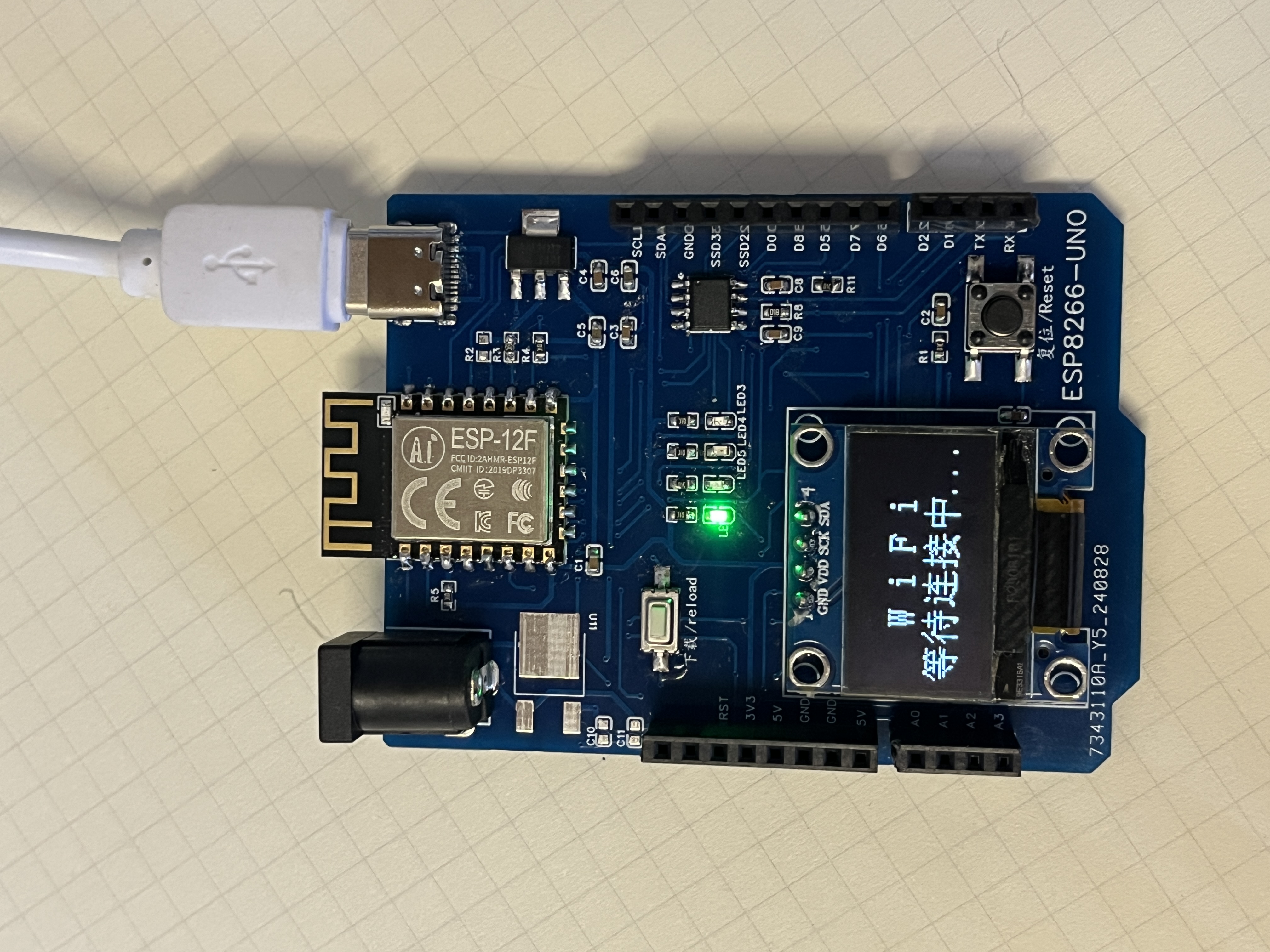
Design a UNO board based on ESP12-F, adding certain analog interfaces and reserving a 0.96-inch OLED display interface.
Video Link:
Bilibili Video -- Function Demonstration and Introduction
Project Overview: This project
designs a UNO-style system board based on the ESP12-F, adding several analog interfaces and reserving a 0.96-inch OLED display interface.
Project Functionality
: The project uses the ESP-12F, adding a 74HC4051 to achieve analog multiplexing, increasing the number of analog interfaces, solving the problem of the ESP8266 having only one AD pin, and reserving an OLED interface. It uses a DC-DC power supply with a maximum input voltage of 35V.
Project Parameters:
The AD section of this design uses GPIO12 (S0) and GPIO13 (S1) as control pins. By switching the high and low levels of these two pins, one AD pin can detect four analog quantities.
This design uses a 0.96-inch IIC OLED display;
this design uses a PJ7805TE, with a maximum input voltage of 35V;
Download Method:
Press and hold the download/reload button to enter download mode, or you can directly modify the schematic to ground GPIO0.
Physical Images :

A demonstration video is provided in the attachment .
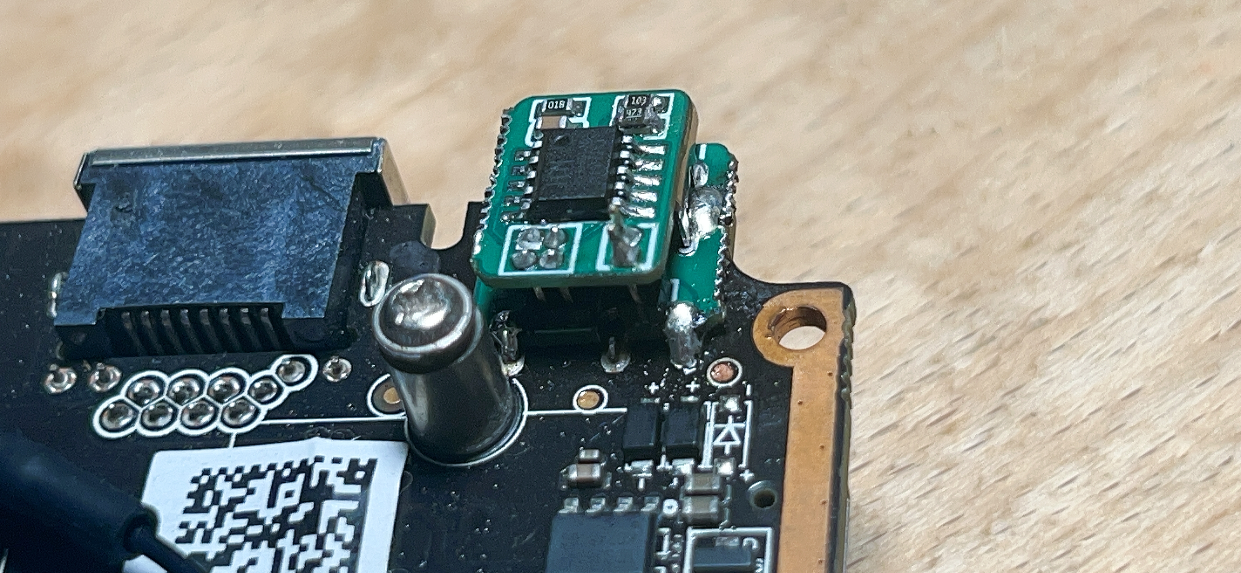
This project is based on the CH224K PD/QC decoy power module. It features non-destructive modification, small size, and compatibility with DC power sockets as shown in the figure.

Note
the use of a stacking method for soldering, employing 1.27 2*2P and 1*2P connections. The soldering technique is important; the bottom pads should be kept as flat as possible. When
prying the board, ensure
it is 1mm thick; thicker boards will be difficult to pry open. Use another board to clamp it from the top and bottom as shown in the figure. Adjust

the voltage selection
and the resistance value of resistor R1 in the white solder mask area.

The finished product is shown in the figure.
PDF_DC converter.zip
Altium_DC adapter.zip
PADS_DC converter.zip
BOM_DC conversion.xlsx
92488
STM32-based temperature and humidity clock
1. Requirements Analysis
: Functional Requirements: Define clock function, temperature and humidity measurement requirements, display method (e.g., LCD or OLED), etc.
Performance Requirements: Response speed, accuracy, power consumption, etc.
Interface Requirements: Identify required input/output interfaces, such as buttons, displays, sensors, etc.
2. Hardware Design
1. Requirements Analysis
: Functional Requirements: Determine clock functionality, temperature and humidity measurement requirements, display method (e.g., LCD or OLED), etc.
Performance Requirements: Response speed, accuracy, power consumption, etc.
Interface Requirements: Identify required input/output interfaces, such as buttons, displays, sensors, etc.
2. Hardware Design:
Selecting a suitable STM32 chip:
Choose an STM32 series microcontroller based on functional requirements, such as STM32F103, STM32F407, etc. Consider processing power, storage space, and peripheral support.
Sensor Selection:
Select a suitable temperature and humidity sensor, such as DHT11, DHT22, or SHT31, etc. Consider sensor accuracy, response time, and interface type (digital or analog).
Display Module Selection:
Select a display screen, such as LCD1602, OLED, etc., based on display requirements and interface type (I2C, SPI, etc.).
Power Management:
Determine power requirements and select an appropriate power management scheme. Consider power stability and power consumption.
Circuit Design:
Use Electronic Design Automation (EDA) tools (e.g., KiCad, Eagle) to design the schematic and PCB layout.
Ensure the design includes necessary power decoupling, circuit protection, and interface connections.
Prototyping and Testing:
Create a circuit board prototype and perform hardware testing to ensure the circuit and sensor function correctly.
3. Software Design and
Development Environment Preparation:
Install and configure development toolchains such as STM32CubeIDE, Keil MDK, etc.
Driver Development:
Write or configure drivers for the temperature and humidity sensor and display module. The STM32 HAL or LL library can be used to simplify development.
Clock Function Implementation:
Implement the real-time clock (RTC) function, configure the STM32 RTC peripheral, and perform time reading and setting.
Data Processing and Display:
Read temperature and humidity data from the sensor and perform data processing (such as calibration and conversion).
Update the display content, including the current time, temperature and humidity information, etc.
User Interface and Interaction:
Implement interactive functions for the user interface, such as button control for time setting and switching display modes.
Debugging and Optimization:
Perform software debugging, check and fix potential problems. Optimize the code to improve performance and stability.
4. System Integration
Hardware and Software Integration:
Integrate the hardware prototype and software system, perform system testing, and ensure all functions are normal.
Functional verification:
Verify the overall functionality of the system, including time display, temperature and humidity measurement, and display updates.
338863f5a1f07cdb7beca64224f86954.mp4
PDF_STM32-based Temperature and Humidity Clock.zip
Altium_STM32-based Temperature and Humidity Clock.zip
PADS_STM32-based Temperature and Humidity Clock.zip
BOM_STM32-based Temperature and Humidity Clock.xlsx
92489
ConLock Dormitory Smart Fingerprint Lock
Are you still troubled by frequently forgetting your keys? Are you still often forced to stay under the eaves of the next dormitory room because you forgot your keys? With this project, you can open the door as long as you have your hands, getting rid of those troubles.
The ConLock
DIY dormitory fingerprint lock's overall
structural design
is shown below

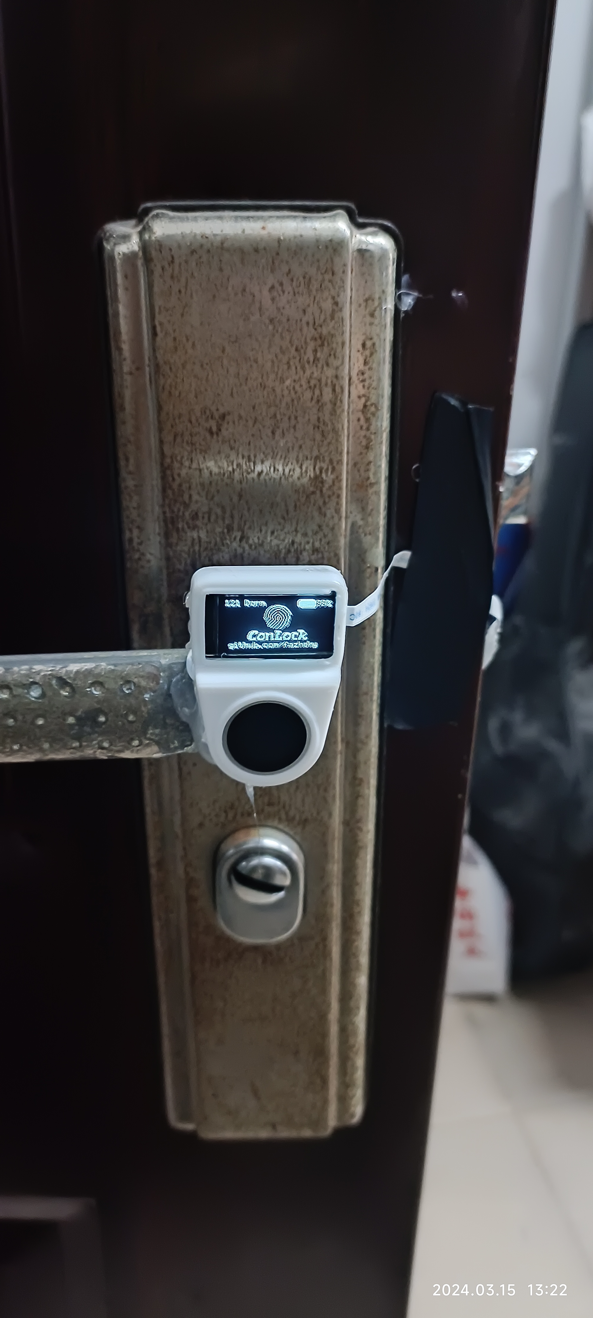
. Some structural notes:
The indoor part is attached to the door using 3M adhesive.
The outdoor part is attached to the door handle using hot melt adhesive.
An FPC cable connects the inner and outer boards; the FPC's thinness won't affect opening the door.
Circuit design
PCB layout files and schematic files are included in the project file. Here, I'll only briefly explain some points to note:
Two 18650 chips are used; the +12V in the main board schematic is actually +8V.
The buck circuit uses the MP2315 chip. Yes, that's right. It's the one Professor Sun open-sourced; long live open source!
The motor driver uses the DRV8870, a single-output and inexpensive
chip. The resistor in the secondary board's OLED circuit can be replaced with a 1mΩ resistor.
The TVS on the secondary board is for ESD protection; I don't know if it's actually effective.
For the software design
, I ported the STM32_OLED open-source library (forgive me for trying to understand those algorithms); the OLED UI was designed using this open-source library. The
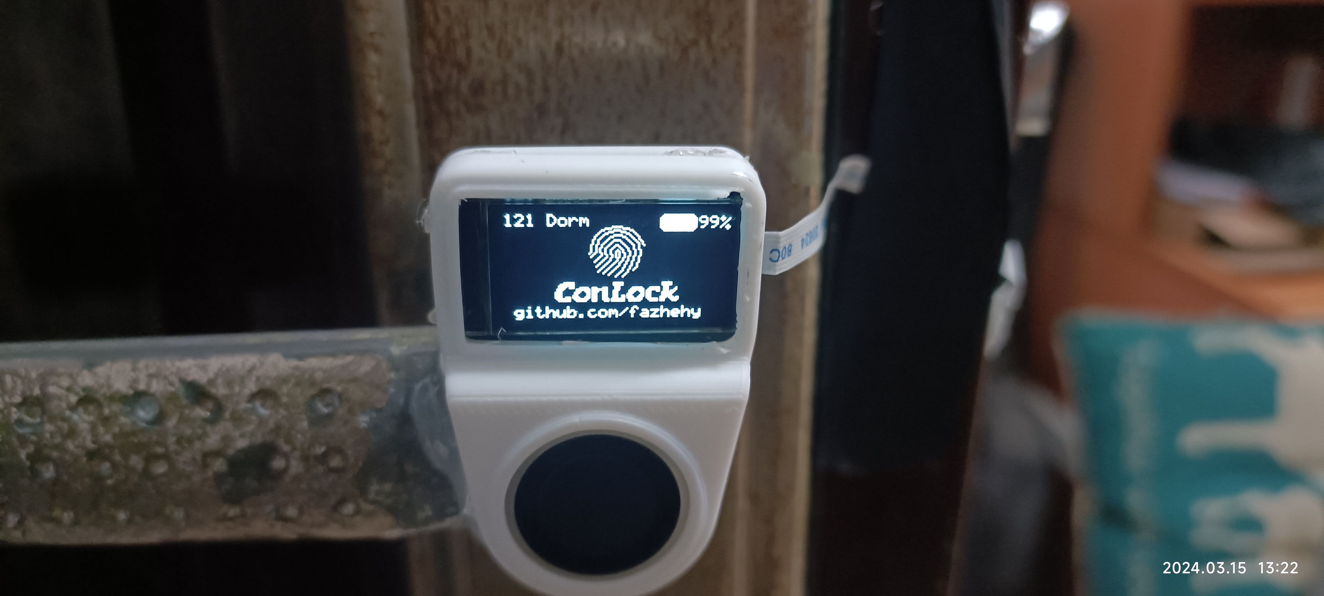
UI changes accordingly for successful and failed fingerprint verification, but I won't include images here.
The battery voltage is acquired using an ADC. If the battery voltage drops below 10%, an alarm will sound when the fingerprint is pressed.
The driver library for the FPM383C (fingerprint module) can be implemented according to the documentation.
An administrator is configured; the first and second people to register their fingerprints become the administrator.
The menu UI is based on MorepUI and is very user-friendly; the link is here.
Standby mode is also included.
Firmware.zip
PDF_ConLock Dormitory Smart Fingerprint Lock.zip
Altium_ConLock Dormitory Smart Fingerprint Lock.zip
PADS_ConLock Dormitory Smart Fingerprint Lock.zip
BOM_ConLock Dormitory Smart Fingerprint Lock.xlsx
92490
C19 handheld console based on ESP32-S3 (compatible with GBC casing)
An open-source handheld console with a GBC form factor based on the ESP32-S3-WROOM-1-N16R8.
This project is a branch of @蕉色幻想's project: A Retro Handheld Game Console Based on the LCSC ESP32S3R8N8 Development Board.
This project aims to achieve a lower cost, therefore cheaper modules are chosen and the header chip is omitted.
Three power supply versions are provided: LDO ASM1117, ME6217C; and DC-DC SY8088.
Regarding materials, please refer to the main project for screen and casing materials; only the modules and power supply (top left corner) differ.
Firmware details are also available in the main project.
This project supports direct USB programming; programming tutorial: Upgrade Device via USB
. This project will not be updated except for hardware bug fixes.
QQ image 20240903170010.jpg
PDF_C19 Handheld Console Based on ESP32-S3 (Compatible with GBC Case).zip
Altium_C19 Handheld Console Based on ESP32-S3 (Compatible with GBC Shell).zip
PADS_C19 Handheld Console Based on ESP32-S3 (Compatible with GBC Case).zip
BOM_C19 Handheld Console Based on ESP32-S3 (Compatible with GBC Case).xlsx
92491
electronic


 京公网安备 11010802033920号

 CTP4018F


