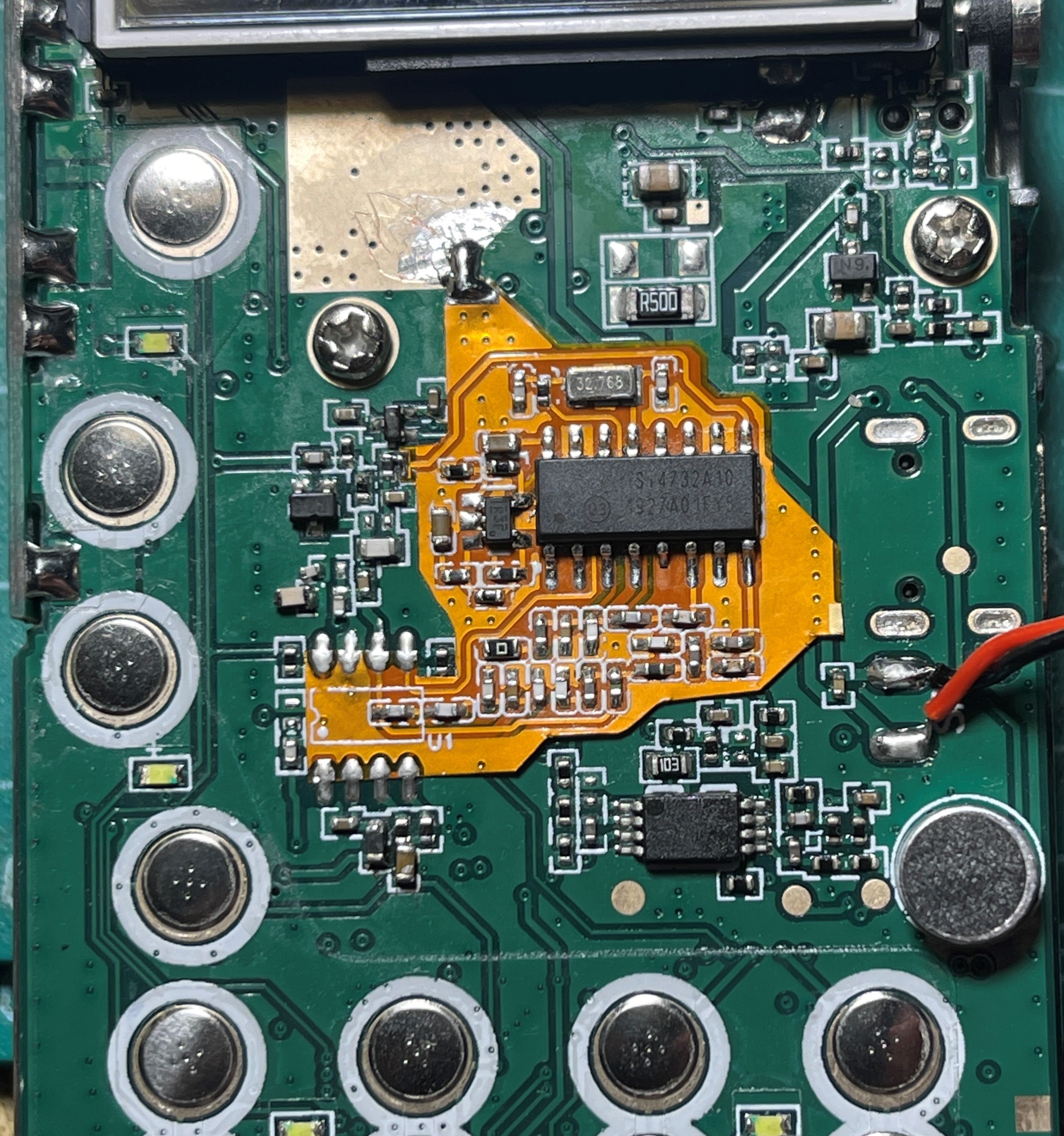
1. The output capacitor of the original R24 transistor amplifier circuit needs to be increased to 10nF or more (point A), and the LC filter at pin 6 of BK1080 needs to be removed (point B).
2. RST is connected to the collector of the power supply transistor (DTA114) of the original R24 amplifier circuit.
1. Due to the loud sound, the AF amplifier chip LMV321 was removed and replaced with a transistor.
2. The high-order bandpass filter in the first version was removed. It was replaced with a 120MHz low-pass filter, then amplified by an LNA, and after passing through a 3rd-order filter for frequency division, it enters the FMI and AMI respectively.
3. An LNA chip AW5007 was added. (In actual soldering tests, this chip is much better than the original R24 amplifier circuit.)
4. The shape was greatly simplified, and a ground wire was inserted between the I2C data line and the RF signal to reduce interference.
Si4732 radio module, with added LMV321 amplification, and a 30MHz low-pass filter and an 80-130MHz band-pass filter.
Uses a 0402 package; proceed with caution if you intend to build this yourself.
Some of the form factors are referenced from free21's project: https://oshwhub.com/free21/si4732-1-1
Note: Due to the small size of the board, it is recommended that the fan drive current not exceed 0.7A. If the current exceeds this, the heat generation will be significant, and heat dissipation needs to be considered.

PDF Mini Type-C Computer Fan Control Board: Make use of your idle computer fan! .zip
Altium Mini Type-C Computer Fan Control Board – Utilize Your Unused Computer Fans! .zip
PADS Mini Type-C Computer Fan Control Board – Make use of your spare computer fan! .zip
BOM_Mini Type-C PC Fan Control Board, put your spare PC fan to good use! .xlsx
93818
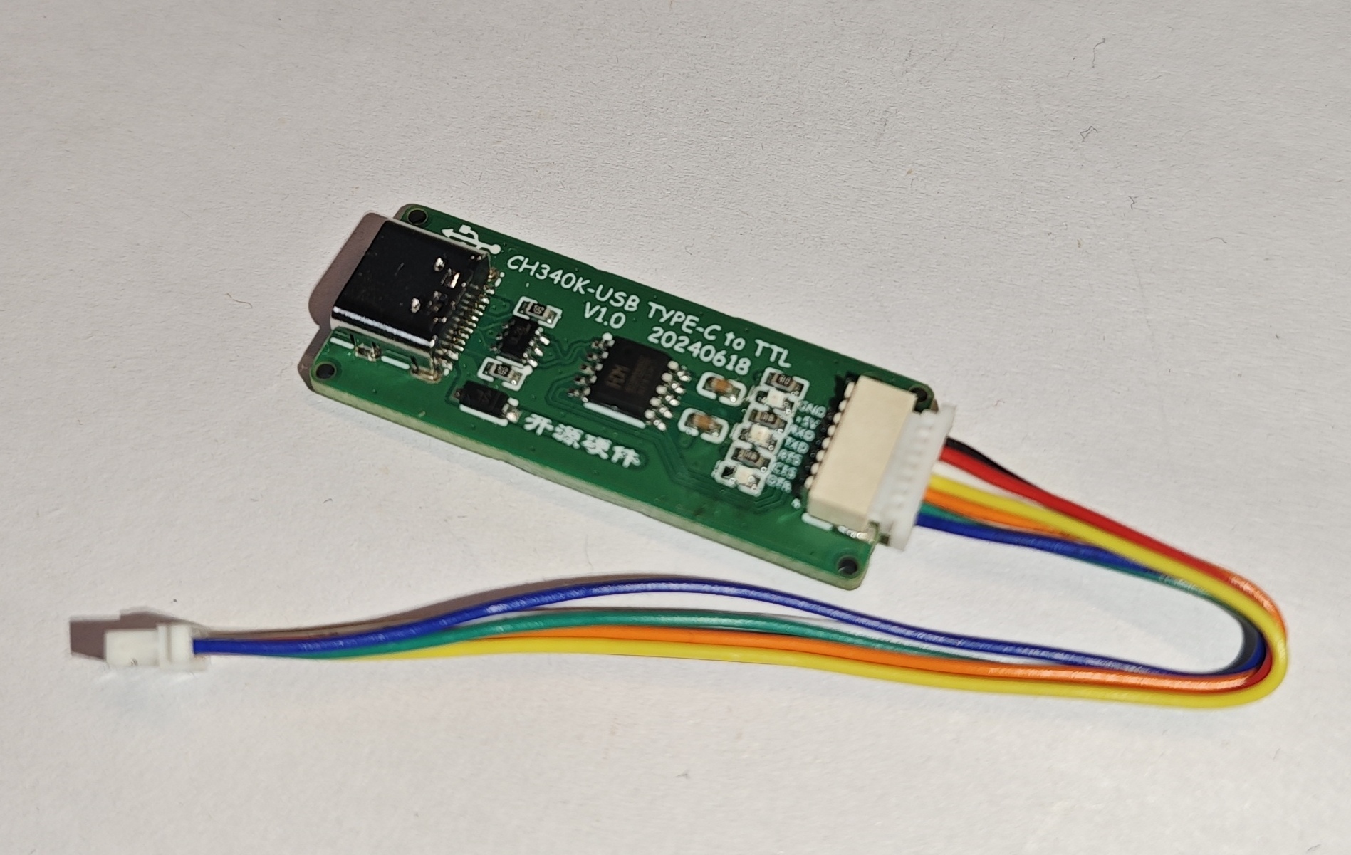
CH340K-USB-TYPE-C to TTL
A serial port debugging assistant designed with CH340K as its core.
Product Introduction:
The CH340K-USB-TYPE-C to TTL module is based on the CH340K chip, featuring an internal crystal oscillator, a maximum baud rate of 2Mbps, software compatibility with the CH341 driver, backflow protection, and corresponding communication and power interfaces. The communication interface includes indicator lights to show the operating status, ensuring stable communication and a compact size.
Product Features:
USB TYPE-C Interface:
Full-speed USB device interface, compatible with USB V2.0.
Fully compatible with serial port applications under Windows operating systems on the computer side, requiring no modification.
Hardware full-duplex serial port with built-in transmit/receive buffers, supporting baud rates from 50bps to 2Mbps.
Built-in firmware; software compatibility with CH341, allowing direct use of the CH341 VCP driver.
Output TTL Level 5V
Pin Function Table
|
No. | Symbol |
Description | |---|---|---|---| |
1
| GND |
Ground pin | | |
2
| 5V
| 5V power supply output pin (maximum 500mA) | |
| 3
| RXD |
Serial data output port |
| | 4
| TXD | Serial
data input port | |
| 5
| RTS# |
MODEM | Handshake output signal, request to send, low (high) active | | |
6
| CTS# |
MODEM | Handshake input signal, clear to send, low (high) active | |
| 7
| DTR# |
MODEM | Handshake output signal, data terminal ready, low (high) active | |
| Product 3D rendering photo |


Product physical photo
PDF_CH340K-USB-TYPE-C to TTL.zip
Altium_CH340K-USB-TYPE-C to TTL.zip
PADS_CH340K-USB-TYPE-C to TTL.zip
BOM_CH340K-USB-TYPE-C to TTL.xlsx
93819
Microbox34
A feature-rich 34-key split keyboard
Microbox34 Split Keyboard
* After using various split keyboards, I designed the Microbox34 myself.
* The main key layout is based on DILEMMA, with optimized thumb key layouts.
* 34 keys; it takes one or two weeks to get used to, but I'm using it myself and it's very comfortable.
* Split design allows for easy adjustment between left and right hands; compact enough to fit in a pocket.
* Controller: ProMicro RP2040 or Promicro NRF52840
* Battery: 401540
* No diodes required, beginner-friendly.
Wireless.jpg
Wired.jpeg
firmware.zip
PDF_Microbox34.zip
Altium_Microbox34.zip
PADS_Microbox34.zip
BOM_Microbox34.xlsx
93820
#Training Camp# Building a Simple Oscilloscope Based on the LCSC GD32 Development Board
A simple oscilloscope based on the LCSC GD32C8T6 development board
Display function: Displays the waveform of the signal graphically, intuitively showcasing the signal's characteristics.
Time and amplitude measurement: Accurately measures parameters such as signal amplitude, frequency, and period.
In engineering, when encountering incorrect waveforms and voltage amplitudes, it was ultimately discovered that the connector had a faulty solder joint.
IMG_4940.jpg
WeChat image_20240328163935.jpg
IMG_5899.MP4
PDF_#Training Camp# Building a Simple Oscilloscope Based on LCSC GD32 Development Board.zip
Altium_#Training Camp# Building a Simple Oscilloscope Based on LCSC GD32 Development Board.zip
PADS_#Training Camp# Building a Simple Oscilloscope Based on LCSC GD32 Development Board.zip
BOM_#Training Camp# Building a Simple Oscilloscope Based on LCSC GD32 Development Board.xlsx
93822
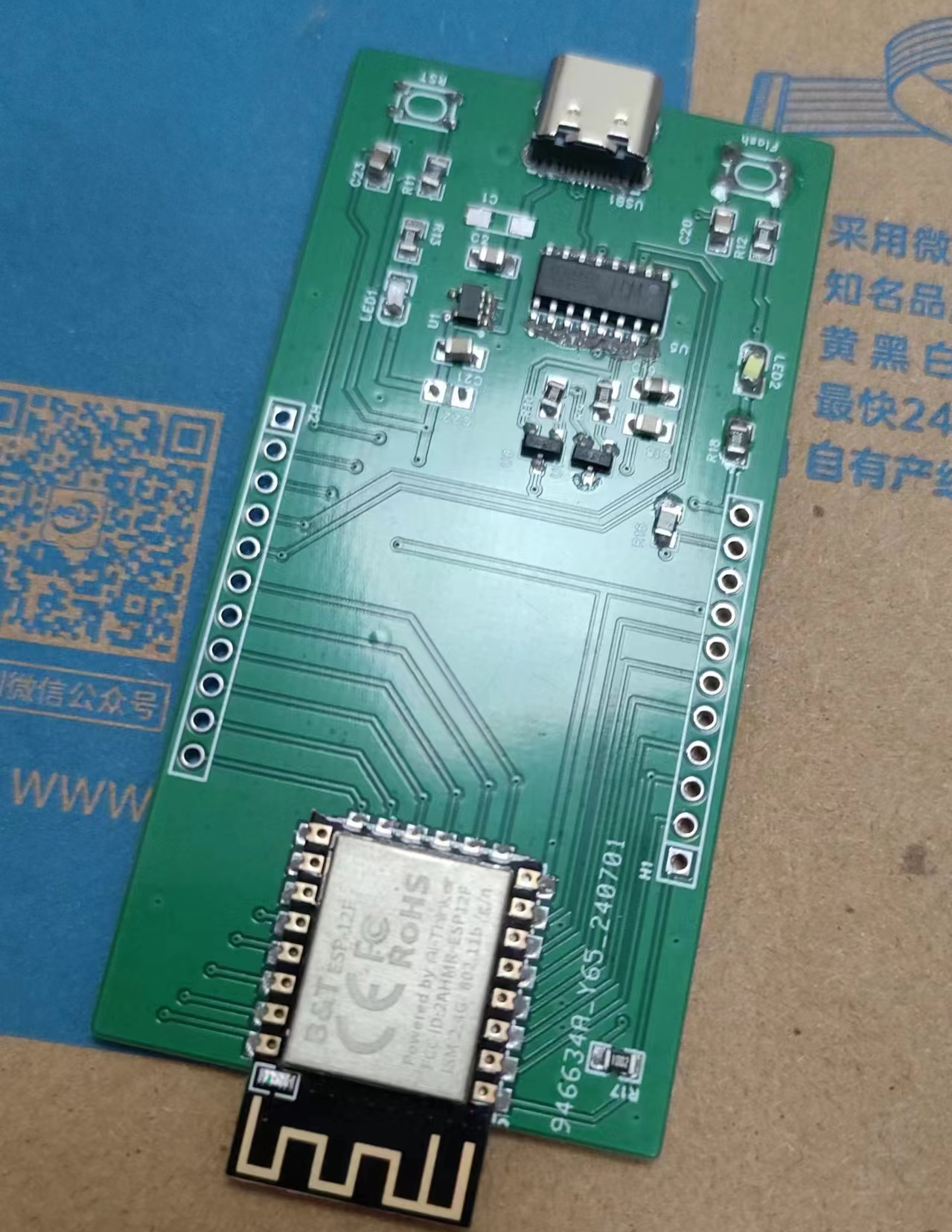
ESP 12F development board
Development board based on ESP8266 12F
Having worked with microcontrollers for several years, I've bought a whole bunch of ESP8266 and ESP32 chips. When I really wanted to tinker with some things myself, I found that NodeMCUs were still too bulky and inconvenient; so I had to build my own PCB.
This is a verification board, and I'll try to share the mistakes I made.
Theoretically, there are already many development board circuits based on the 12F, so I won't go into detail, but it's still worth mentioning in practice.
Many circuits use resistors like 10k, 4.7k, etc., seemingly without any major standard. In actual testing, I found that many 10k resistors could be replaced with 1k. For example, replacing the 10k resistor on IO2 with a 1k resistor makes it brighter; replacing the 10k resistor on the EN string with a 1k resistor significantly reduces the startup and operating time of the automatic download circuit.
Due to manually applying solder paste, I encountered a subtle soldering problem (which I discovered later), causing the microcontroller to frequently power on, with the power LED on and the IO2 LED dimly lit, but without any response. It could detect the COM port, but couldn't program anything. Various tests revealed that EN+3.3V... After shorting, IO2 goes out, and programming can proceed normally. It runs normally after programming, but sometimes it inexplicably reverts to a state where it cannot run or program.
After various circuit tests, a process of elimination was used: the resistor on EN was removed and directly shorted; the J3Y resistor in the automatic download circuit was removed, and the 10k resistor was replaced with a 1k resistor, etc. Finally, it was discovered that the problem might be with the solder paste on the J3Y. After resoldering the J3Y, the problem disappeared. This process took two days to find the cause, because the automatic download circuit of J3Y had worked normally before, so J3Y was not suspected.
If your automatic download circuit works, but requires a longer time... It is recommended to adjust the resistor in series on EN to 1kΩ, which will allow for near-instant download. A 10kΩ resistor might take two seconds to start working, and the time could be even longer if the circuit malfunctions.
The power supply circuit no longer uses the ams1117 because it requires tantalum capacitors; instead, the ME6211 is used, which only requires one 1uf capacitor for both input and output – very simple. Therefore, although the design shows two capacitors for input and output, only one is actually used.
This is a verification board; no minimization or optimization is performed.

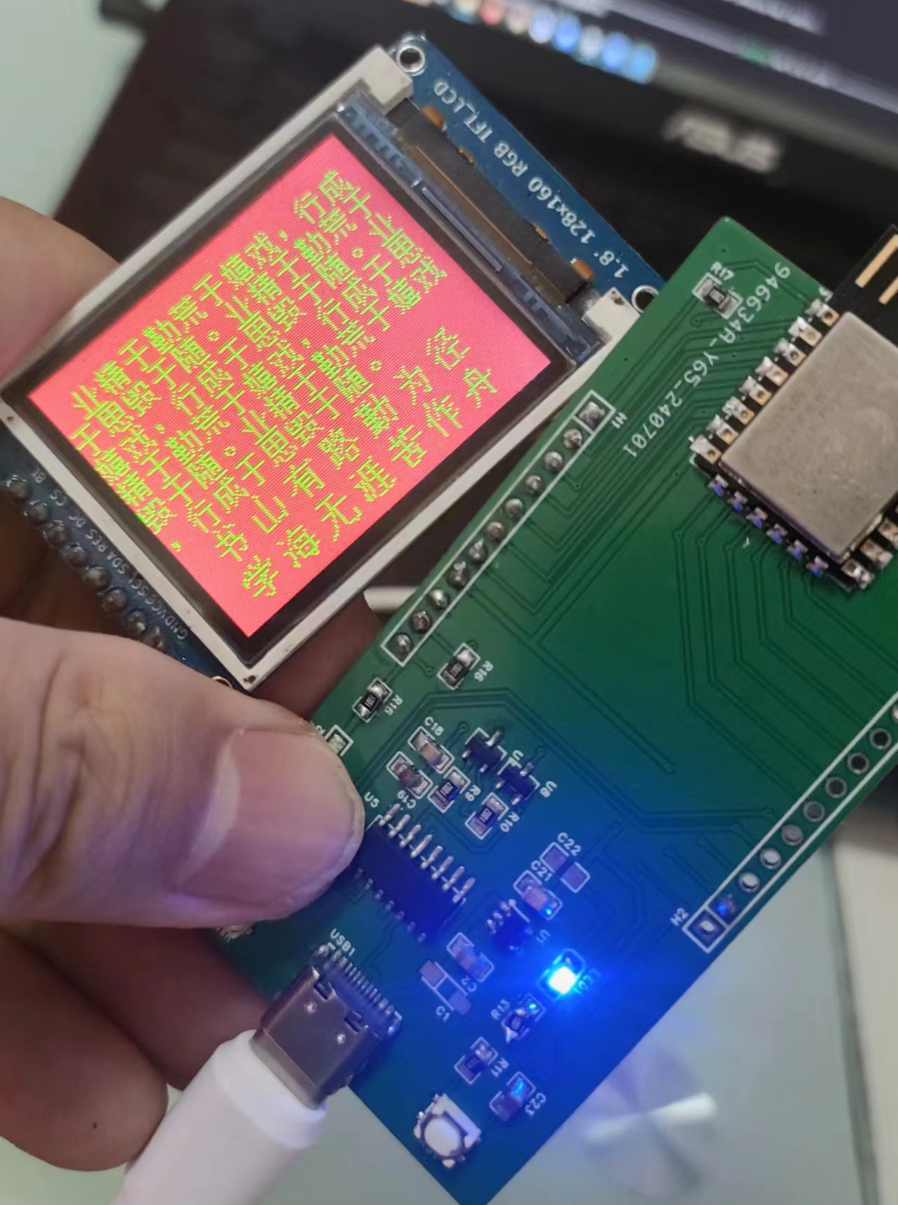
It works normally, and SPI also works correctly.
I'm not good at hardware, but I'm good at software. I used my own custom Chinese character library, a 200+KB library with over 7000 characters;
https://github.com/StarCompute/tftziku.
The 8266 has too few GPIOs; after providing SPI, there are no more ports. This board was built purely for practicing with ESP32.
For those with more money, SMT is recommended for board building.
PDF_esp 12F Development Board.zip
Altium_esp 12F development board.zip
PADS_esp 12F development board.zip
BOM_esp 12F Development Board.xlsx
93823
electronic
 Second version:
 Version 1:
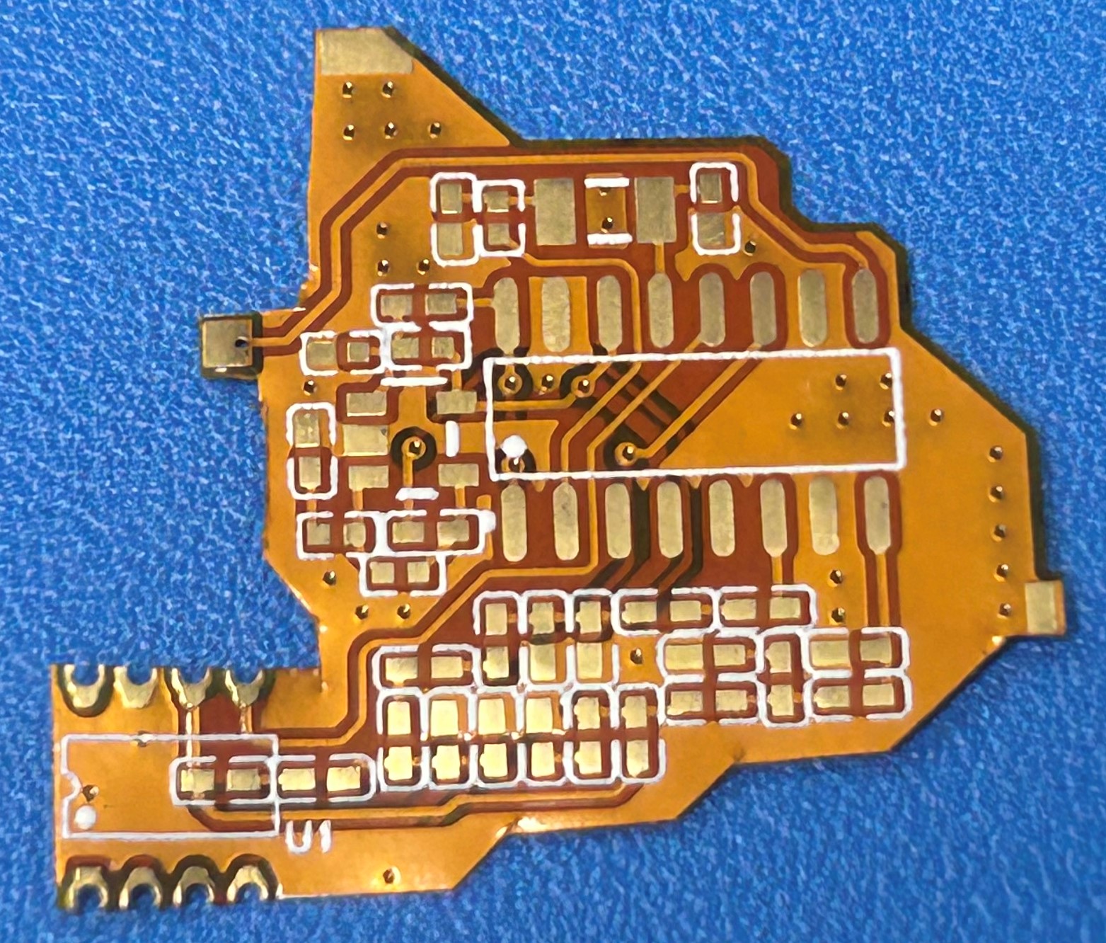


 京公网安备 11010802033920号

 AN29000A


