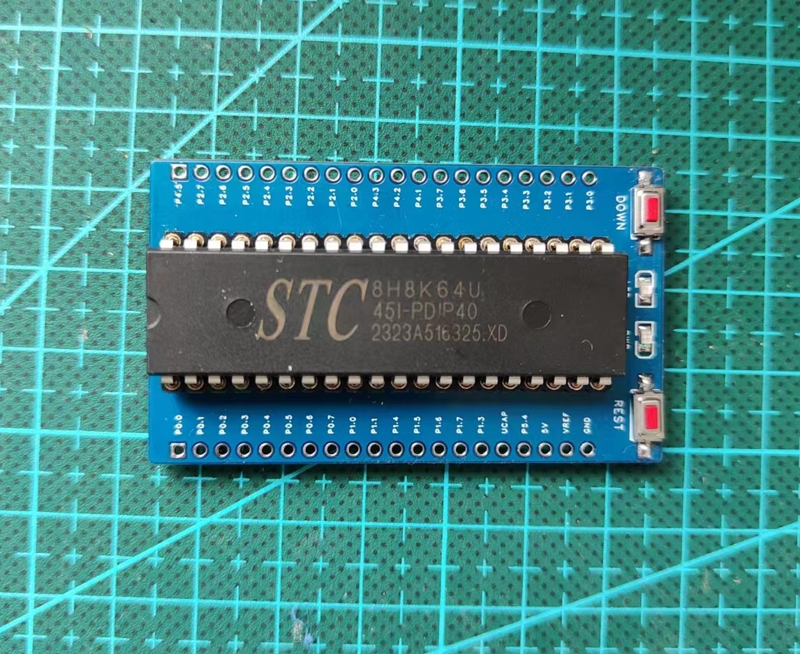
The STC8H8K64U minimal system supports USB emulation and USB download, which is very convenient. I've tested the USB-CDC function and the built-in debugging interface of STC-ISP, making it particularly suitable for this minimal system. Basically, a Type-C port is all you need.
It also allows for uninterrupted ISP download, eliminating the need for frequent plugging and unplugging for downloads and restarts.
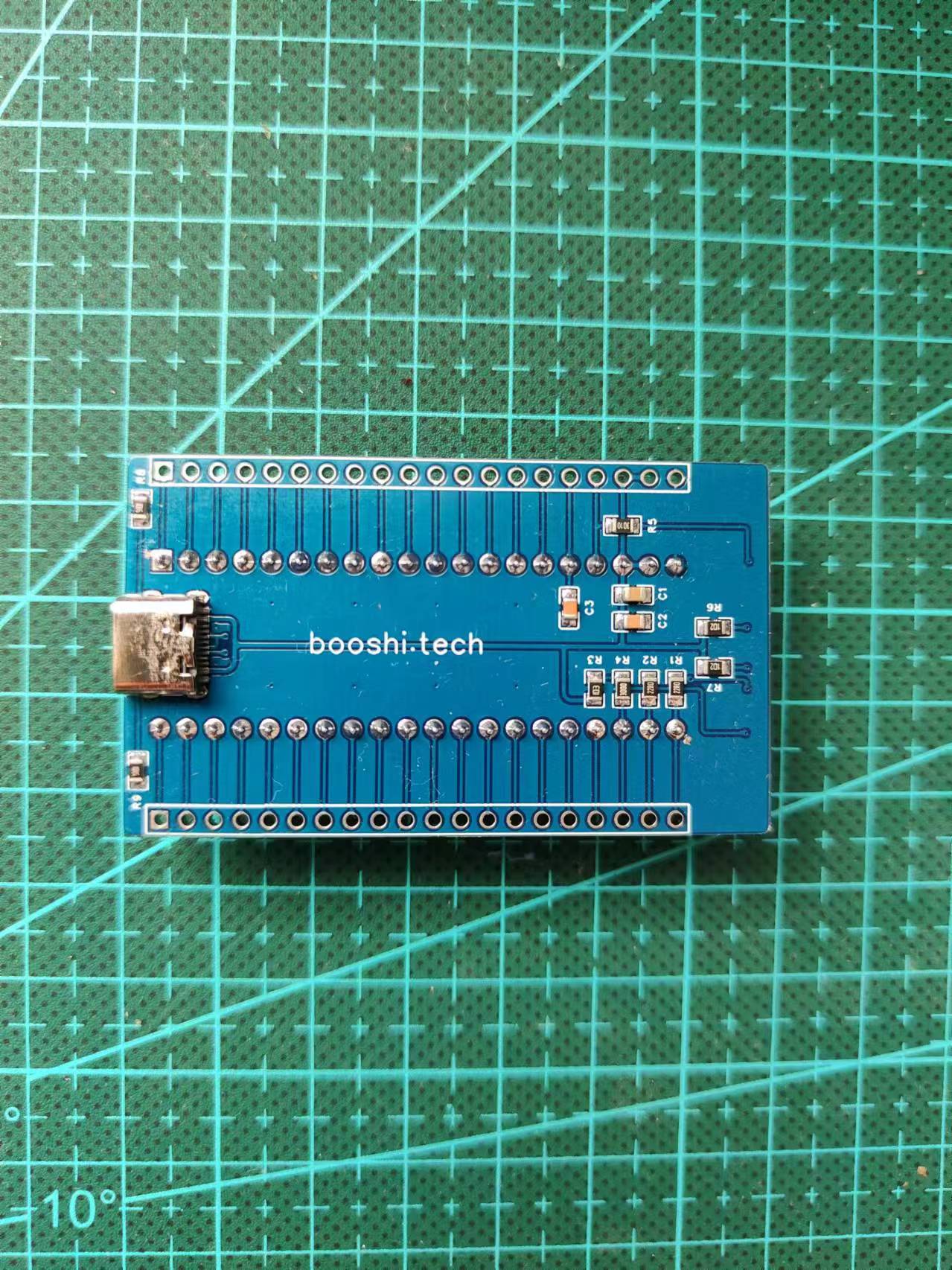
Two PCB versions are available, the only difference being the presence of mounting holes. I recommend prototyping the version with mounting holes, as I found the lack of holes inconvenient and added them. A 3D-printed casing would add a lot of refinement.
USB Download:
1. Download the latest STC-ISP (https://www.stcai.com/gjrj)
2. Press and hold the DOWN button, then insert the USB cable.
3. In STC-ISP, you should see "STC-USB Writer (HID1)" displayed on the serial port scan, indicating that USB download is successful.
Soldering Instructions:
For aesthetic purposes, the Type-C interface and most components are located on the back (back of the actual product photo, top of the PCB). Therefore, when soldering, use a soldering iron to solder the Type-C side first. The buttons and LEDs on the other side can be soldered directly with a soldering iron without much difficulty.
Actual Product Image:
The pin markings in the actual product are too small; the latest version has enlarged them.
PDF_[Verified] STC8H8K64U Minimal System.zip
Altium_[Verified]STC8H8K64U Minimal System.zip
PADS_[Verified] STC8H8K64U Minimal System.zip
BOM_[Verified]STC8H8K64U Minimum System.xlsx
94402
3D Printed Miniature RC Excavator Circuit Part v2
3D printed mini RC excavator V2 - Circuitry section: The remote control and receiver board are included in the project. Remember to use the latest version.
The joystick has been optimized, and an OLED screen has been added. The solution has been changed to STM32F0 + CI24R1.
The first version had many issues, so the second version optimized
the LDO by replacing it with an XC6206, which is cheaper and more reliable!
Aluminum electrolytic capacitors are no longer used indiscriminately. Instead,
OLED with PMOS control is chosen based on the manual's recommendations, with the buttons connected to the wake-up pin, for easier low-power design later.
Issues with the CH340 have been rectified
, and the position of the controller and OLED screen has been slightly adjusted .
Version v2.2.2
considers using JLCPCB SMT's version,
making some optimizations to the first version,
and using the internal v2.3.0 version. Only the latest version will be used!
PDF_3D Printed Miniature RC Excavator Circuit Part v2.zip
Altium 3D Printed Miniature RC Excavator Circuit Part v2.zip
PADS_3D Printed Mini RC Excavator Circuit Part v2.zip
BOM_3D Printed Miniature RC Excavator Circuit Part v2.xlsx
94403
BM3451 Battery Equalizer Board V2.0
Each battery has protection features, including short circuit protection, overcurrent protection, and NTC high temperature protection.
This 18650 protection board uses
6 18650 lithium batteries
to output 24V
and features short-circuit protection, overcurrent protection, and undervoltage protection.
The entire project is open source
and requires no coding. All hardware components are included
. It is used with T12 soldering irons and C245 soldering iron power supplies.
The project files are as follows:


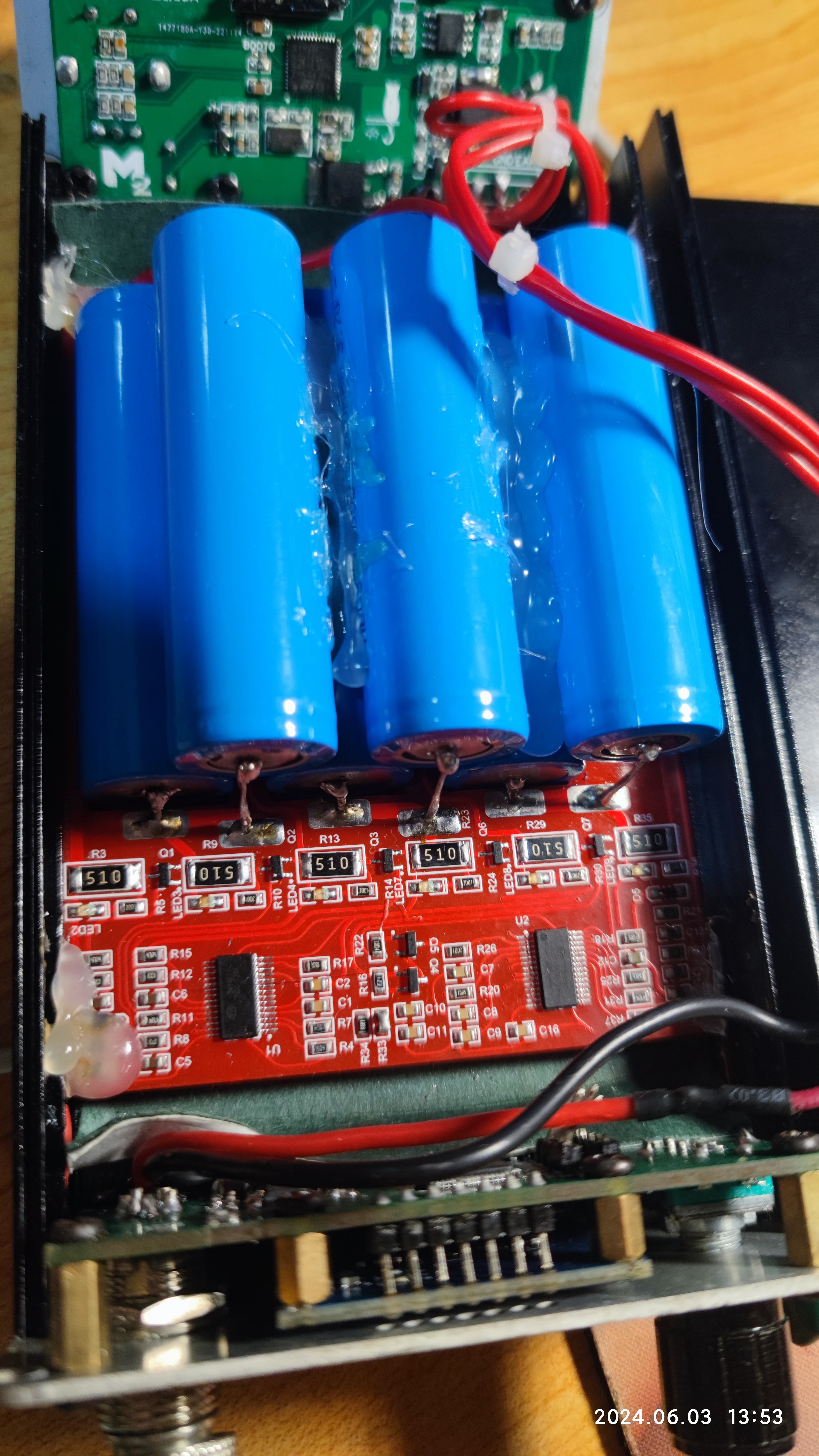
Updated June 2, 2024, V2.0: Improved wiring standardization, enlarged battery holes for greater stability, and most importantly, free sample size
testing. We welcome your feedback and suggestions for improvement.
PDF_BM3451 Battery Balancing Board V2.0.zip
Altium_BM3451 Battery Equalizer Board V2.0.zip
PADS_BM3451 Battery Equalizer Board V2.0.zip
BOM_BM3451 Battery Balancing Board V2.0.xlsx
94404
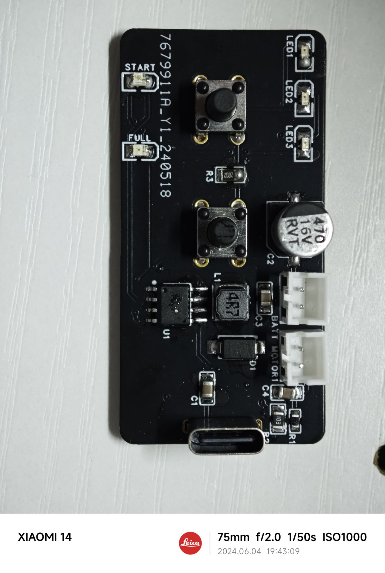
Portable fan
A portable fan with three speed settings and rechargeable function.
This portable, rechargeable fan features three speed settings and is powered by one or two 18650 batteries. It uses the LP78070F motor driver chip. It has five LEDs, three speed indicator lights, two charging indicator lights, and two touch buttons: one for speed switching and the other for reset. The power supply and motor interface use a 2mm pitch PH2.0 female connector for easy connection and maintenance.
The overall structure was modeled in AutoCAD and manufactured using a 3D printer with PLA filaments. Two motor base models are available: a flat-bottomed brushless motor base and a standard 130 motor base.

The 3D-printed fan blades were too rough, so they were purchased from Taobao; the default blades are 100mm in diameter with a 2mm aperture.
The 18650 battery holder is built-in using a model and connects to the battery using 18.5*16.5mm spring contacts. The two batteries are connected in parallel, allowing for the use of one or two batteries.
Portable fan demonstration video.mp4
3D Printing Files.zip
model file.zip
PDF_Portable Fan.zip
Altium_Portable Fan.zip
PADS_Portable Fan.zip
BOM_Portable Fan.xlsx
94405
Microscope supplemental light
A fill light suitable for 0745 lenses, using 5mm LEDs with built-in current-limiting resistors, fixed with hot melt glue.
It saves those who need it ten minutes of drawing time. Even if the drawing is terrible, they can fix it themselves if needed. It's not something that requires much skill.
PDF_Microscope Fill Light.zip
Altium_microscope fill light.zip
PADS_Microscope Fill Light.zip
BOM_Microscope Fill Light.xlsx
94406
6S Charger Balance Board
6S Balance Board for Model Airplane Remote Control
The design is simple: just make a prototype and solder on the XH2.5 connector.
Balance boards bought on Taobao usually have plug-in connectors, and it's not easy to remove the connector and resolder the leads if you want to remove the balance cable connector through the hole. Therefore, I redesigned the
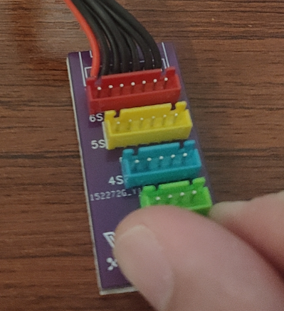
back. After soldering and cutting the leads, it's best to cover it with 3M foam tape to prevent electric shock or short circuits during use.
PDF_6S Charger Balance Board.zip
Altium_6S Charger Balance Board.zip
PADS_6S Charger Balance Board.zip
BOM_6S Charger Balance Board.xlsx
94407
Pocket Fan
In the sweltering summer, how can you do without a pocket fan that you can carry around in your pocket?
The main feature is its compact fan size, making it pocket-sized and portable. It features 555 PWM speed control, with an internal resistor for adjusting the speed ratio. An external variable resistor further enhances the speed adjustment. The fan operates at 5V/0.2A (4025 fan), and a single 18650 battery provides approximately 8 hours of maximum power operation. Its small size, slightly smaller than a mobile phone, allows for easy pocket carrying. The casing is included in the accessories.

5V fan housing v27.stl
Fan cover v4.stl
PDF_Pocket Fan.zip
Altium_PocketFan.zip
PADS_PocketFan.zip
BOM_Pocket Fan.xlsx
94409
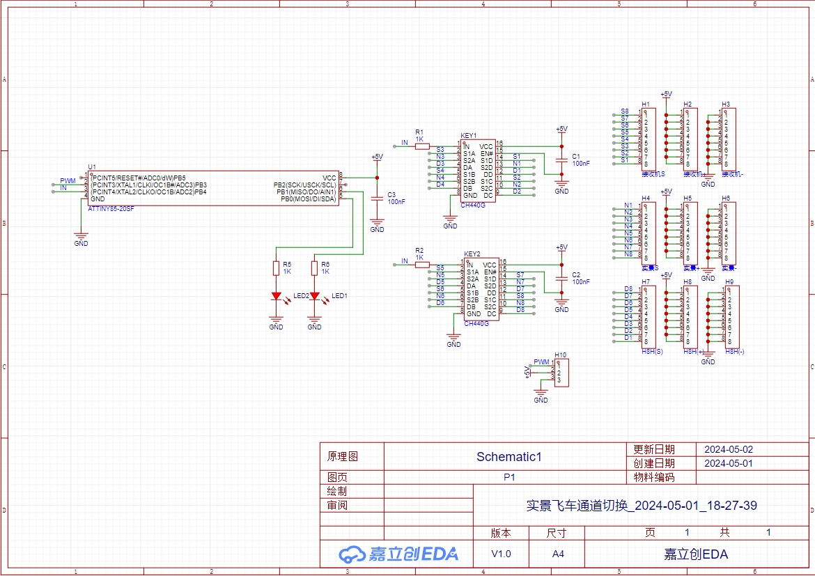
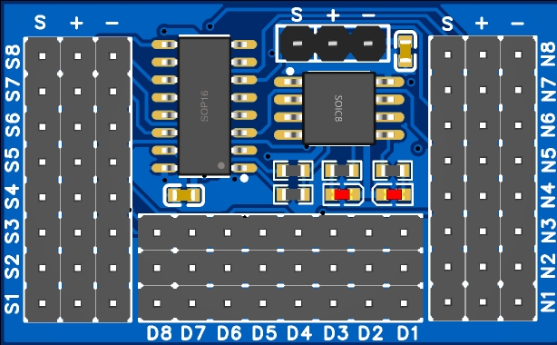
Real-world car chase lane switching_2024-05-01_18-27-39
Two inputs and one output 8-channel PWM signal switching module
Module control IC: ATtiny85, operating clock frequency 16MHz.
The program burning file is in the attachment.

Blink.ino.hex
PDF_Real-world Racing Track Switching_18-27-39.zip
Altium_Real-world Racing Track Switch_18-27-39.zip
PADS_Real-world Racing Track Switch_18-27-39.zip
BOM_Real-world car track switching_2024-05-01_18-27-39.xlsx
94413
SU-22T Offline Voice Development Board
Verification of the SU-22T module with intelligent mechanism, low power consumption, and direct connection to CH340C for downloading programs via Type-C.
1. SU-22T physical image

. 2. Improvements compared to the CI-03T offline voice development board: CI-03T development board link.
1. Replaced the speaker interface PH2.0 female connector for easier plugging and unplugging (the previous PH2.0 connector was too tight, causing damage to the PH2.0 wires during plugging and unplugging).
2. Added a diode between the communication lines of CH340 (TXD) and SU-22T (RXD) to prevent CH340 from flowing back current into SU-22T.
3. SU-22T program download instructions
will be added later; see the development package below for details.
4. Note
that D2's placement is not ideal, so you need to solder it together with the module and CH340. Do not solder D2 last, as the space is too small. If you have a hot air gun, then disregard this, hehe!
SU-22T Development Kit.zip
PDF_SU-22T Offline Voice Development Board.zip
Altium_SU-22T Offline Voice Development Board.zip
PADS_SU-22T Offline Voice Development Board.zip
BOM_SU-22T Offline Voice Development Board.xlsx
94414
LED Display
The main purpose of this array of lights is to check whether the components of the microcontroller are functioning properly after soldering.
I recently built several minimum system boards, and after finishing the microcontroller, they looked quite nice under fluorescent lights. However, one day I happened to hold one up to the sun and noticed some adhesion between the joints. This inspired me to create a board with integrated lighting to inspect the soldering of each joint. The board has a simple structure and can be directly fabricated. It can also be adjusted to meet specific needs.
PDF_Light Display.zip
Altium_Light Display.zip
PADS_LED Display.zip
BOM_Light Display.xlsx
94415
electronic


 京公网安备 11010802033920号

 VHD144T20KTCR2FAB


