I. Team Introduction
Personal: Shenlong Zaizai
II. Development Background
It's truly frustrating. I bought so many USB to TTL adapter modules, it's driving me crazy. Burning circuit boards, burning serial ports... they all break down after a few days. Although they're quite cheap, the constant failures are unbearable! I designed my own serial programmer that can stably output TTL levels, so it can be used continuously, infuriating those unscrupulous vendors (who send broken products and refuse returns).
These are actually quite cheap, probably less than 3 yuan each, while a CH340G chip might cost more. Indeed, in the industrial electronics era, the cost of transporting materials is higher than the materials themselves.

But today I want to talk about its problems.
First, its advantages:
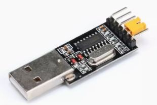
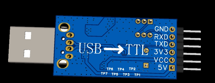
The design idea of this module is a classic one, integrating the 3.3V and 5V power supply outputs of the CH340G chip, corresponding to 3.3V and 5V levels. The materials used are top-notch (saving costs). The output TTL signal level voltage can be converted using the yellow jumper cap on the back.
It's perfectly compatible with all STC microcontroller series, unlike the PL2303 solution which has download issues due to driver problems (this is very stable).
It not only has a power LED but also TXD and RXD LEDs, making it easy to visually check if communication is working properly during product use.
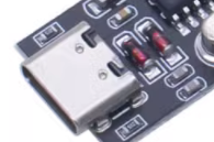
It supports 32-bit or 64-bit systems like WIN7/WIN8/WIN10/SERVER 2008. It cleverly utilizes the two 4148 chips shown in the diagram to complete the 5V to 3.3V (normally 3.4V).
Now for its drawback:
the critical flaw of this module lies in the cost-effective voltage conversion of these two 4148 chips.
Normally, with a 5V input, the voltage is reduced by using two diodes and their internal resistance voltage drop (approximately 0.7V). In high-voltage applications, multiple diodes are usually connected in series for voltage division. However, in practical applications, it's unclear whether this is a problem with the 4148 chips themselves, or if some manufacturers use high-quality 4148 chips (with small voltage drops). This can cause abnormal output voltage. The highest I measured was around 3.7V, and the lowest was when the module suddenly stopped working. (The reason was that there was a voltage between one of the diodes and another diode, causing one of the diodes to remain off and not conduct. I measured the voltage with a multimeter, and it worked again. The module's power indicator light came on.) If you encounter this module malfunctioning, you can test it. Generally, the CH340G chip is quite reliable (unless the firmware is lost).
Getting back to the main point, experienced technicians know that if you read the manual, you'll find that whatever voltage VCC provides, the corresponding RX and TX voltage levels are roughly the same. If this voltage level is higher than 3.6V, it will definitely burn out. Secondly, when the serial port is sometimes not used or needs to be disconnected, we usually only disconnect the USB end. In this case, the board will supply power in reverse (I suspect that my abnormal voltage was caused by this, resulting in abnormal voltage levels across the diodes and preventing them from working).
The faults of this product are basically all in the diodes. If you measure the diodes individually, they are fine; a voltage of 5V is not enough to break down and damage the diodes. However, if you measure the chip's input voltage under USB power, you'll sometimes see no 3.3V input, and the power indicator light will be off. But when you measure the voltage between the two diodes to ground, the module will magically light up again. It's not a matter of discharging or removing power. (I've tried this; this indicates a damaged diode, and I recommend replacing it. However, I've found that new diodes might be of very high quality (low voltage drop), resulting in a very high 3.4V output voltage, so be careful.) In other words,
if it's not broken, why would you buy a new one? If the indicator light doesn't light up, you assume it's faulty and replace it. If the computer can't find the driver or it doesn't pop up, you assume it's faulty. Actually, it's all a problem with the diodes; unstable or abnormal power supply leads to abnormal output.
III. Design Summary:
I wanted to improve this aspect to make the 3.3VTTL stable and avoid burning out the board's serial port.
For easier testing, I added a one-click cable switching function, making it convenient to switch the RX and TX lines by pressing a button in case of incorrect connections.
I don't want to be ripped off anymore. Even though it's not expensive individually, my board is expensive, and I only have one for testing. If it breaks, I have to fix it myself.
IV. Problem Analysis
and Reference Technical Manual: I found that the V3 pin of the chip
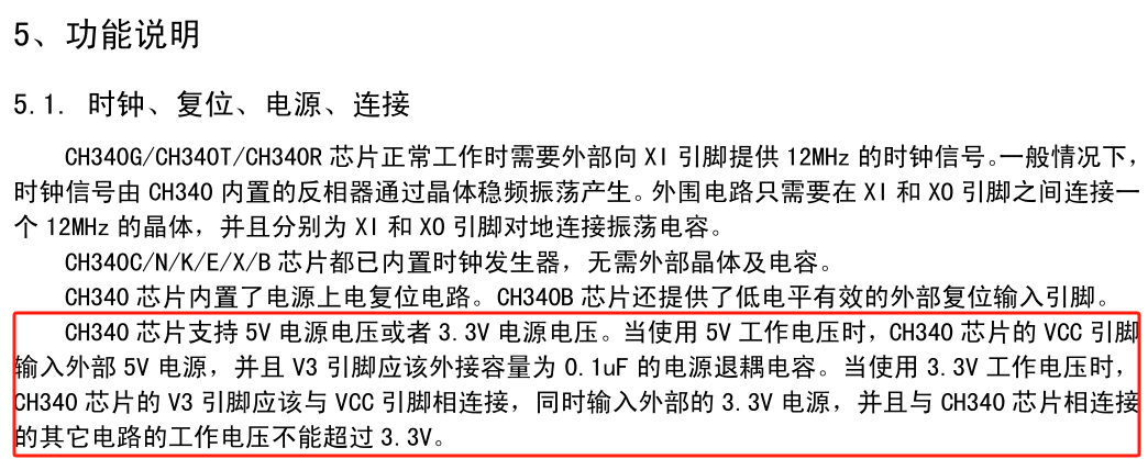
is best used to control the TTL 3.3V input voltage; otherwise, it's prone to failure.
Other pins are rarely used, so I've designed them to be exposed for those who need them. Those who don't need them can leave them as is; they look nice.
V. Overall Design Block Diagram

: Below is the schematic diagram for design reference.
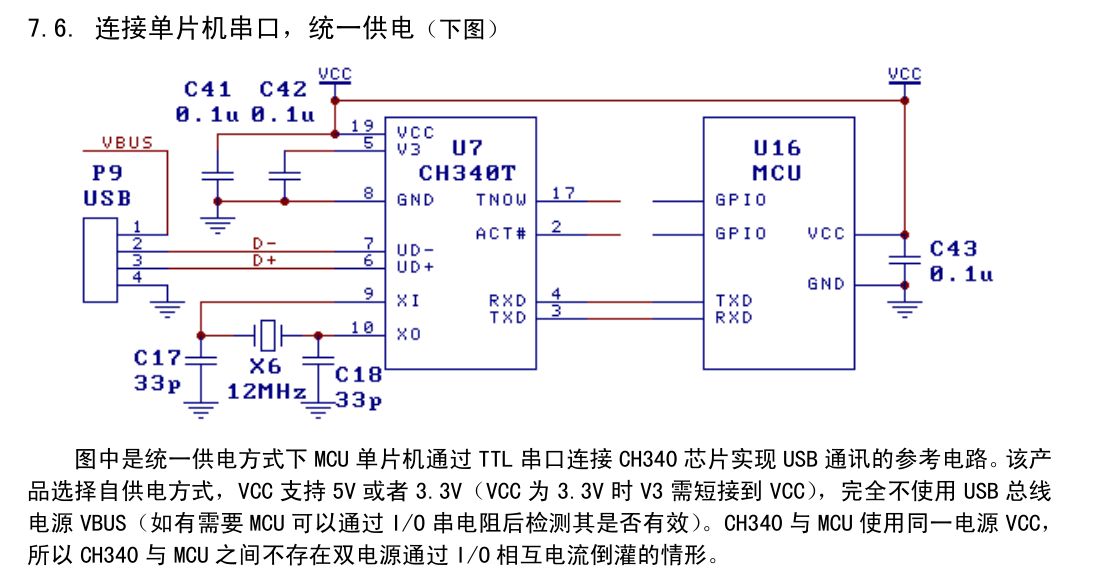
When designing, pay close attention to the V3 pin.
VI. Hardware Circuit Composition:
First and foremost, modify the power supply to ensure a stable 3.3V output. 5V USB power is actually quite stable. My first design used an LDO + diode reverse current protection design, but the voltage was too low. It only reached 2.7V and couldn't pick up.
Later, I switched to a diode + LDO. Testing showed that the LDO could supply 5V in reverse without problems. I was initially worried about the LDO being sensitive to reverse power supply, so I designed it that way. Therefore, what you see here is the second, improved version.
The LDO is powered by 5V single-phase power, and the actual measured output voltage is around 4.6V (1117-3.3). In actual use, it can output 3.3V normally, which is very stable. The power supply is solved.
The one-click cable replacement function uses a double-locking switch to achieve RX/TX switching of the output, which is perfect and has been tested.
VII. Program Flowchart:
Pure hardware, no software, and no software operation interface.
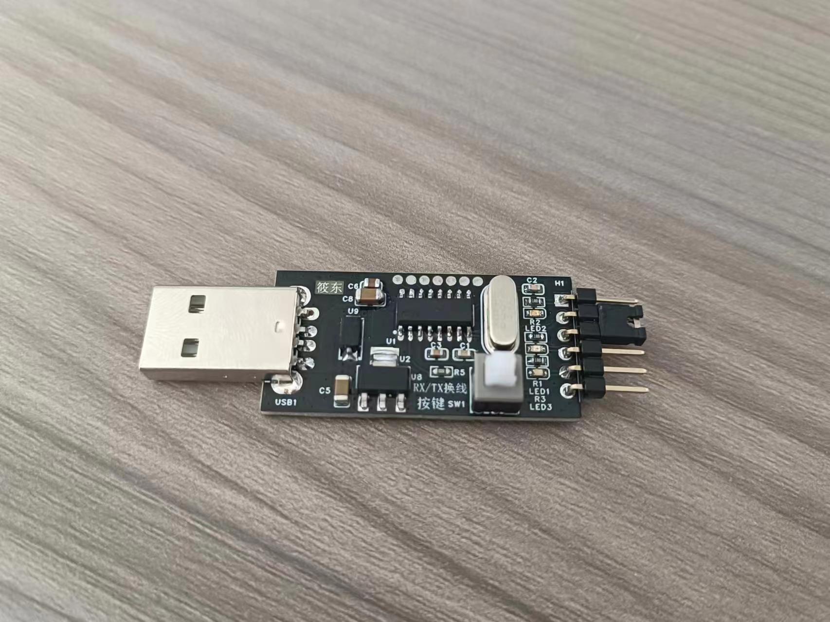
VIII. Physical Display:
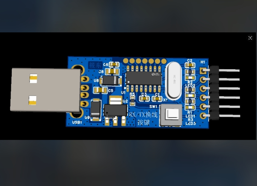
The back looks a bit abrupt, but it is indeed the smoothest way, and the relationship and direction are consistent.
The physical product is still good.

IX. Precautions :
1. Other designs are reserved on the board, and I have perfectly integrated the two LDO packages.
2. In order to make others' paths unusable, a compatibility design has been made. It is also possible to use a diode + diode step-down method. As long as you think it is okay, I will not force everyone to use it. It is up to you. It is mainly for friends who need to replace broken modules. You can directly port it to my board to experience the one-click cable replacement function and other pins.
3. V3 requires special attention to the pin connection method. I've seen some open-source projects neglect this. When designing for 5V and 3.3V compatibility, they need to consider reverse power supply and shared power issues, just like I have.
4. Let's exchange ideas if we have any questions. I hope vendors will see this too. This is really painful!
X. Demo
Video I've put the demo video at the end; the effect is very good. Recorded with one hand, please understand.


 京公网安备 11010802033920号

 MI-P7WY-MYV


