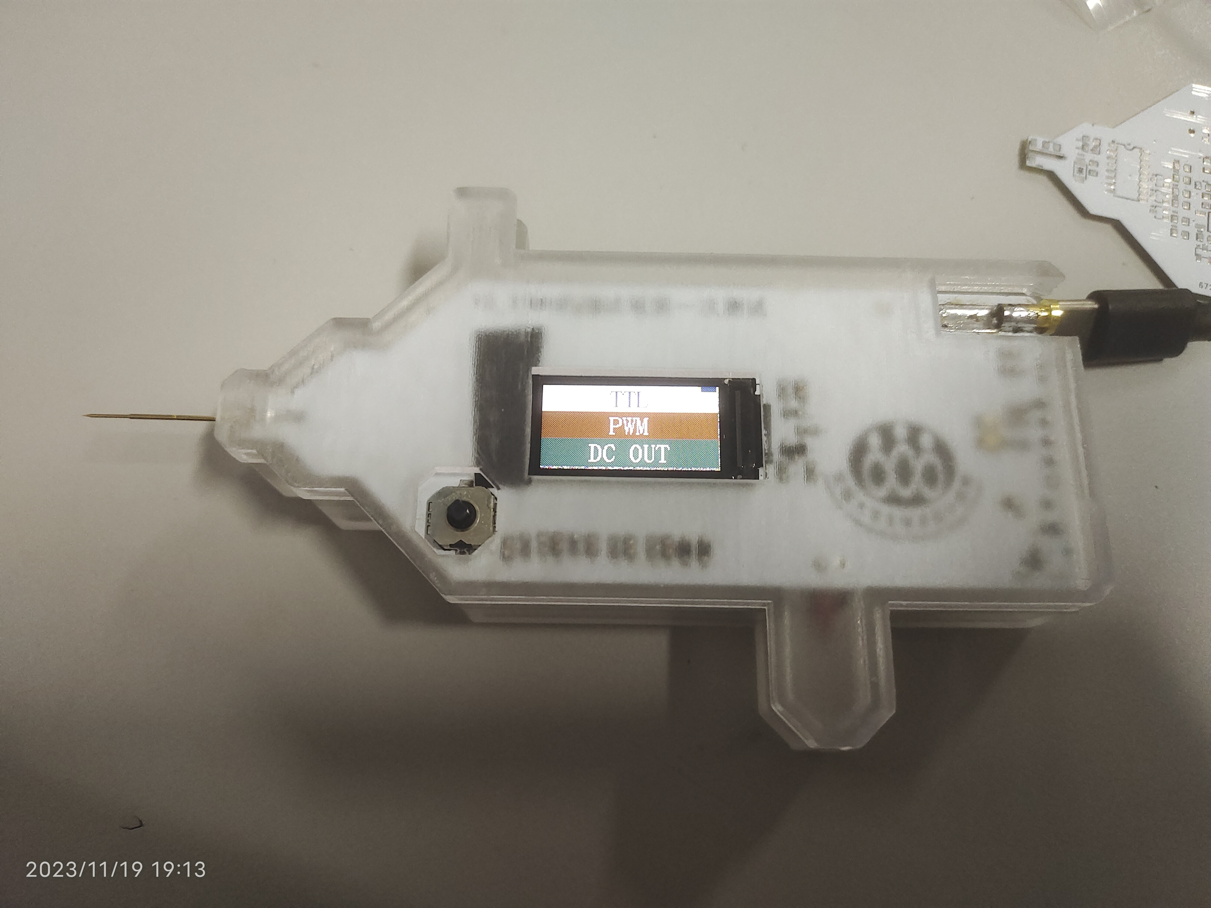
I'm a complete novice when it comes to replicating He Diangong's CW32 test pen
, and I kept running into problems. I had the same issue last time I participated in a Renesas clock-related event. Fortunately, the experts in the group provided guidance and helped me complete the replication. This time, I encountered many problems, such as the screen driver not working, the charging module overheating, and the chip not downloading. With the help of the experts in the group, I solved them one by one
. 1. For the screen driver issue, first check the soldering quality for any cold solder joints or incorrect soldering. Then, use a multimeter to check for short circuits. Mine was short-circuited due to improper soldering,
causing the screen not to light up. 2. The charging chip, TP4057, was overheating. Increasing the resistance in the PROG circuit reduced the current, and the chip naturally stopped overheating.
3. For the chip download problem, first carefully read He Diangong's documentation, and then connect the wires correctly in the programming settings as described in the documentation. If you have time, watch the official CW32 videos on Bilibili; they are very comprehensive and support domestic 32-bit microcontrollers.
Thanks to JLCPCB training camp.
I redesigned the PCB without modifying the original open-source schematic. It's important to separate analog and digital grounds. When designing the board, consider how to solder and test it after it's installed. Include extra test holes to prevent accidents. Also, during soldering, check for short circuits after soldering a section.
I highly recommend replicating the test pen. You'll learn a lot during the replication process, and the pen itself is very useful – it's excellent!
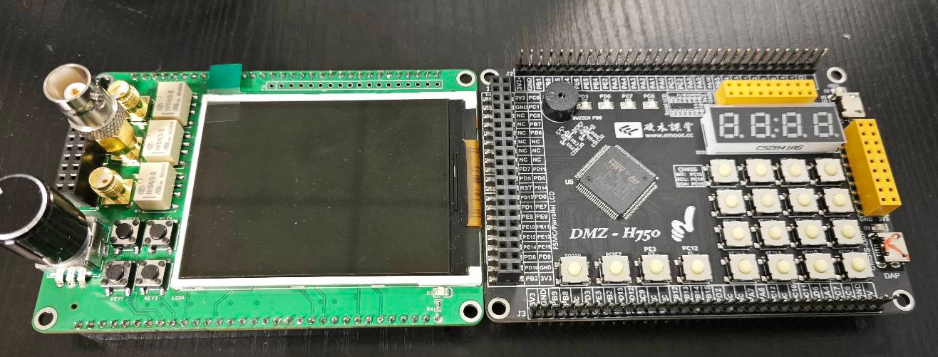
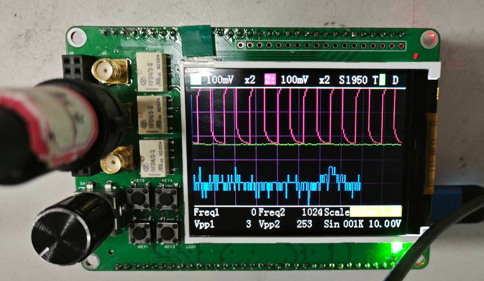
Oscilloscope & Signal Source Analog Front-End Expansion Board for Use with H750 Core Board
This project replicates the Hardwood Classroom AFE03 oscilloscope signal source expansion board.
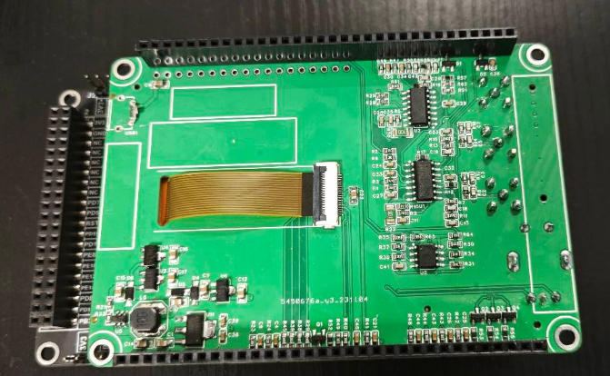
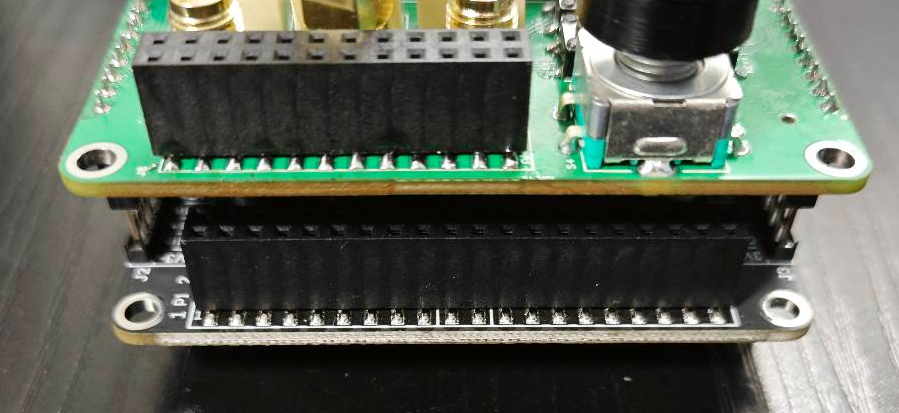
Physical images of the split-type design
:
Front
, back
, and side

views:


Hardware components:
Implementation of the signal conditioning circuit:
Below, we will briefly introduce the analog input and output channels on the AFE03 board. We will then discuss the design and calculation methods in detail.
Analog input channel introduction:
This includes signal conditioning implemented through resistor voltage dividers and operational amplifiers, and a square wave output implemented through a comparator (for triggering and frequency measurement).

INA, INB: The input terminals of the oscilloscope. The pocket instrument sends an analog signal to this point. Here, a 1MΩ input impedance is achieved through a series resistor voltage divider, generating two signals for selection: one is a direct input, and the other is attenuated to 1/20.
gain: A selection switch that selects either the direct signal or the signal attenuated to 1/20 to enter the first-stage non-inverting amplifier. The non-inverting amplifier performs two tasks: first, it amplifies the input signal at the non-inverting terminal by a factor of two; second, it shifts the amplified signal by 1.65V, calculated as Vo = 1.65 + 2*Vi. Therefore, the overall gain of the corresponding circuit is 2 times or 1/10 times.
AnalogA and AnalogB: The analog signals, amplified and shifted by the inverting amplifier, are connected to the STM32H750 development board and enter the H750's ADC.
TrigerA and TrigerB: The square wave signal generated by AnalogA, AnalogB, and the DC reference level (generated by one of the H750's DACs) after passing through a comparator enters the STM32H750's timer for frequency measurement.
DAC_OUT2: The DC reference level is output through the STM32H750's internal DAC2 configuration.
Analog output channel description:
Includes signal conditioning implemented by resistor dividers and operational amplifiers, and a square wave output implemented by a comparator (for triggering and frequency measurement).
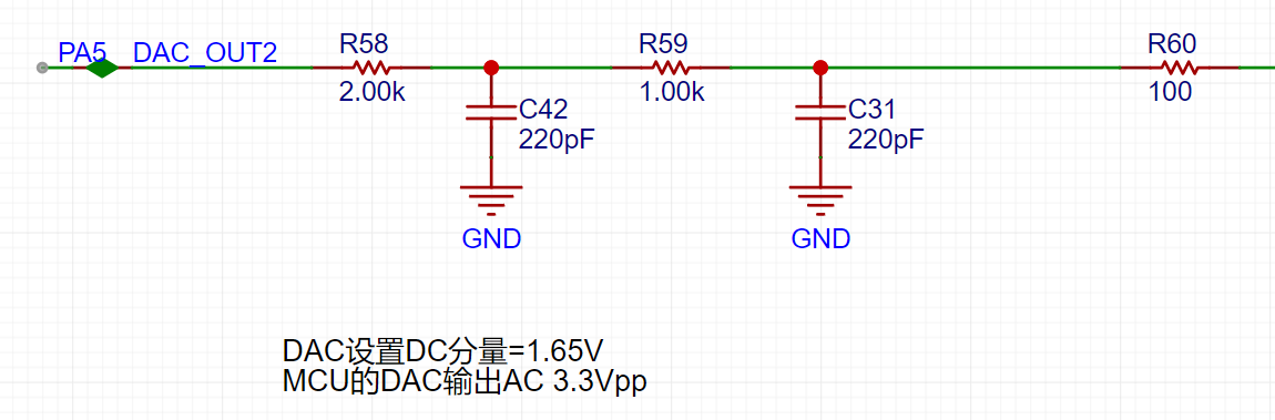
The STM32H750's DAC1 output has a waveform range of 0-3.3V.
A second-order RC filter implements a low-pass filter function.
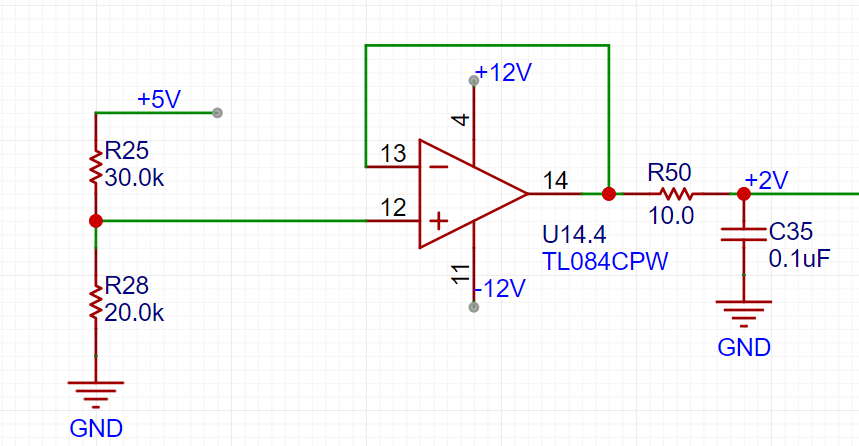
A resistor divider and buffer convert the 5V input to a low-impedance 2V output, which is then amplified by -5 times for shifting the output signal.

The output amplifier performs two functions: first, it amplifies the non-inverting input by 6 times; second, it shifts the amplified signal by -10V before outputting it. The calculation formula is Vo = -10 + 6 * Vi.
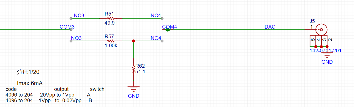
The voltage divider network is used to achieve good results when outputting small signals by utilizing analog circuit voltage division.
Below, we will introduce the calculation of the analog circuit in detail:
Analog Input Channel Calculation:
This section requires some basic knowledge of operational amplifiers.
First, we need to understand that when the VREF of the STM32H750 is powered by 3.3V, the input range of the STM32's ADC is 0-3.3V, while our maximum input signal is ±15V. Therefore, we need to solve the problem of large signal input not saturating. Let's solve an equation:
15 * a + b = 3.3
- 15 * a + b = 0,
which gives a = 0.11 and b = 1.65.
This means we need to attenuate the input signal to at least 0.11 times (approximately 1/9), and then add 1.65V DC to meet the full-scale input of the ADC. Therefore, we use the following operational amplifier circuit. The resistor network achieves 1/20 attenuation, and the operational amplifier performs a 2x amplification and a 1.65V voltage shift, thus achieving 0.1INB + 1.65V.
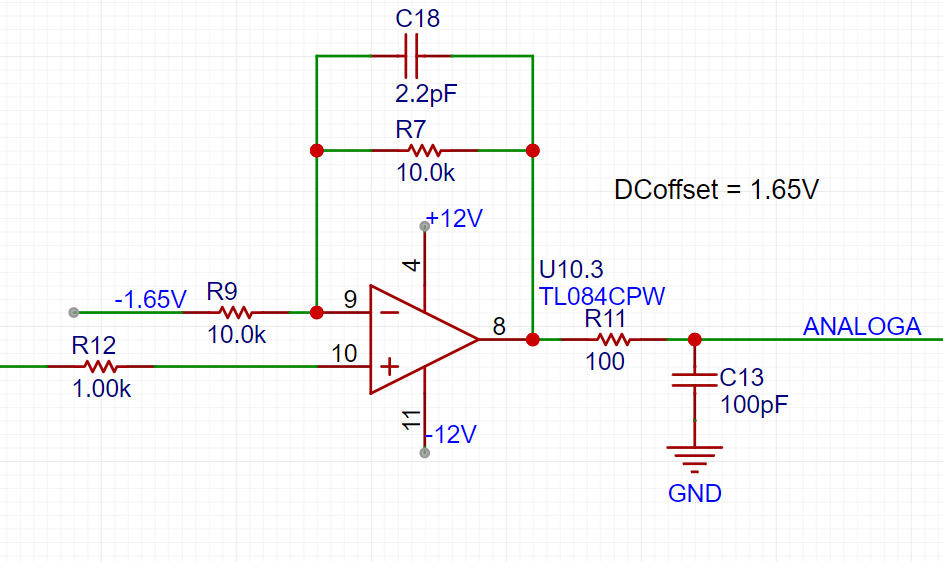
We can use the superposition theorem to analyze this circuit. First, when analyzing the contribution of the input signal INB to the output Vo, we ground the other voltage source in the circuit, -1.65V. This way, the input signal is divided to 1/20 after passing through R14 and R18, and then amplified by a factor of 2 by the non-inverting amplifier circuit. The overall gain of the input signal is 1/10. When analyzing the contribution of -1.65V to the output, we ground the input signal AIN, and the amplification factor of -1.65V is -1. Therefore, we obtain the output Vo = -1.65V * (-1) + AIN/10 = 1.65V + AIN/10.
The -1.65V above is obtained from -12V through a resistor divider and buffer.

This circuit solves the problem of matching the ±15V input to the ADC's 0-3.3V input range. We also need to consider accurate sampling even with small input signals. For example, a 10mV signal will attenuate to 1mV after passing through this circuit. To maximize the signal-to-noise ratio of the input signal, we add a switching mode to the analog front-end. When acquiring small signals, the switch selects the direct input of INB to the non-inverting input of the op-amp, instead of selecting the attenuated signal from INB. This ensures the signal entering the ADC is as large as possible. Combined with a 16-bit ADC, this ensures accurate and reliable sampling results.

As shown in the diagram, we add a signal switch (relay or manual switch) after the 1M ohm input voltage divider resistor to select whether INB enters the op-amp's non-inverting input directly or after being divided by 1/20. Both methods result in a 1M ohm input impedance for INB. When we need to acquire small signals, we can toggle the switch to use the direct input for more accurate measurement results.
We can calculate that when the direct input is selected, Vo = 2AIN + 1.65, and when the attenuation input is selected, Vo = AIN/10 + 1.65.
Analog output channel calculation:
When the VREF of the STM32H750 is powered by 3.3V, the output range of the internal DAC is 0-3.3V. To achieve the ±10V output required in the problem, we need to solve the following equations:
0*a + b = -10V
3.3*a + b =
Solving for 10V , we get a=6.06 and b=-10
, which allows us to design the following circuit:

In the diagram above, the 0-3.3V signal output from the STM32H750's internal DAC is filtered by a low-pass filter and then input to the non-inverting input of the TL082, forming a non-inverting amplifier with a gain of 6. The amplified waveform is 0-19.8V. Then, utilizing the -5x amplification capability of the TL082's inverting amplifier section, the +2V obtained from the 5V voltage divider is amplified by -5x to obtain -10V. This -10V is then superimposed on the 0-19.8V signal output from the non-inverting amplifier to obtain an output of approximately ±10V. The calculation formula is: Vout = 6*Vin -10.
Similar to an ADC, to ensure the signal source output covers ±10mV to ±10V, while simultaneously balancing a large signal range and small signal accuracy, the DAC's resolution is a crucial factor. The H750's DAC is 12-bit, and its full-scale output (using all 4096 code values) is ±10V. When outputting small signals by reducing the DAC code value, to achieve a 7-bit voltage resolution (128 vertical points), the waveform must be attenuated by 128/4096 = 1/32. This translates to an output voltage range of ±10V/32 = ±0.3215V. For signals smaller than ±0.3125V, further reducing the code value results in insufficient DAC resolution and noticeable waveform steps. Therefore, we use analog voltage division. When outputting signals smaller than ±0.3125V, we use a switching resistor divider to attenuate the waveform by 1/20, ensuring sufficient voltage resolution for small signals. Simultaneously, the combination of R57 and R62 ensures a 50Ω output resistance at 1/20 attenuation, and R5 ensures a 50Ω output resistance at the x1 range.
Comparator Circuit:
To implement the trigger and frequency counter functions, we designed two comparator channels on the board. These channels convert the waveforms of the two analog input channels before they enter the ADC into square wave signals for use as timer inputs in the H750. The reason for using the waveforms before entering the ADC is that the waveforms entering the ADC, after conditioning by the front-end analog circuitry, fall within the known 0-3.3V range, making the comparator's comparison threshold design easier.
As shown in the diagram above, the H750 uses its internal DAC2 to output a 0-3.3V DC signal, which is compared with the waveform of channel 2 before entering the ADC, converting the channel 2 waveform into a square wave. This allows the H750's timer function to use the square wave signal for interrupt handling and timer capture.
Software Part:
From Hardwood Classroom's open-source code.
PDF_Oscilloscope & Signal Generator Analog Front-End Expansion Board for Use with H750 Core Board.zip
Altium Oscilloscope & Signal Generator Analog Front-End Expansion Board for H750 Core Board. (zip)
PADS_Oscilloscope & Signal Generator Analog Front-End Expansion Board for H750 Core Board. zip
BOM_Oscilloscope & Signal Generator Analog Front-End Expansion Board for Use with H750 Core Board.xlsx
Replace all the 0805 resistors and capacitors in the original design of the CY7C68013 logic analyzer (https://oshwhub.com/Starry/luo-ji-fen-xi-yi) with 0603 resistors and capacitors (I had extras on hand).
When soldering the CY7C68013, whether it's a disassembled chip or a new one, it's best to tin the pins (I soldered it twice, but it still didn't work when plugged into the computer, so I even bought a new chip online). Apply solder paste to the pads, use a hot plate or hot air gun, and apply solder paste to any bridging areas with a soldering iron.
The dimensions are 20*45 cm, which is quite noticeable compared to the size of a palm.
After connecting, install the driver (you can install as administrator by right-clicking). Open CyConsole.exe, click Options to open the EZ-USB interface, click S EEPROM, and select the saleae.iic file to burn. If using a larger capacity EEPROM, click Lg EEPROM.

Download the burning software here: PulseView saleae.


PCB Logic Analyzer (copy_2023-11-4.html)
CYC68013.zip
PDF_CY7C68013 Logic Analyzer - 20_45 copies_0603 RC version.zip
Altium_CY7C68013 Logic Analyzer - 20_45 copy_0603 RC version.zip
PADS_CY7C68013 Logic Analyzer - 20_45 copy_0603 RC version.zip
BOM_CY7C68013 Logic Analyzer - 20_45 copy_0603 RC Version.xlsx
97136
Mini 5-axis motherboard with 2225 driver
A 3D printer motherboard with an STM32F103C6 main controller, a 5-axis TMC2225 driver, and stepper motors, and a 410 rod hub.
First, thank you to the user "琉璃" for their hard work in creating the wiring. This is a mini 3D printer motherboard that requires a tool head to function. An open-source 3D printer motherboard with an STM32F103C6 main controller, a 5-axis TMC2225 driver for stepper motors, and a 410 stick hub is also available.
Welcome to join the discussion group: 948104146
PDF_Mini 5-Axis Motherboard with 2225 Driver.zip
Altium Mini 5-Axis Motherboard with 2225 Driver.zip
PADS Mini 5-Axis Motherboard with 2225 Driver.zip
BOM_Mini 5-Axis Motherboard with 2225 Driver.xlsx
97137
CPU PCB
Columbia Spring 23 EE6350 design project team08: A18 Bionic
PCB design of NPU
Columbia Spring 23 EE6350 design project team08: A18 BionicPCB design of NPU
PDF_NPU PCB.zip
Altium_NPU PCB.zip
PADS_NPU PCB.zip
BOM_NPU PCB.xlsx
97139
[Original*] Color silkscreened STM32F407VET6 basic system version
This is a system board with a serial port based on the STM32F407VET6, made as a personal hobby.
Image source: Pixiv artist.

I have absolutely no experience with Photoshop. This is my
first open-source project, and I integrated it using Windows Paint. Please forgive
any shortcomings. The schematic was copied and slightly modified. It's
an STM32F407VET6 minimum system board (with USB serial port ). The
serial
port uses a CH340C
microcontroller with a built-in 1.5A self-resetting fuse for protection against sudden failure .
PE14 and PE15 are for programming control LEDs (ice blue) and a 5V LED (blue).
Please ensure the power supply voltage does not exceed 5V. I didn't consider the power supply issue when designing the CH340C serial port circuit.
I hope to provide more advice for beginners.
I don't have a hot plate or low-temperature soldering wire, so please don't ask me if my soldering is bad. This board floats as soon as I apply solder when connected to the network.

video_20231114_213834.mp4.JPG
video_20231114_213834.mp4
IMG_20231114_113507.jpg.JPG
IMG_20231114_185426.jpg.JPG
IMG_20231114_185430.jpg.JPG
PDF_【Original_】Color silkscreened STM32F407VET6 basic system version.zip
Altium_【Original_】Color silkscreened STM32F407VET6 basic system version.zip
PADS_【Original_】Color Silkscreen STM32F407VET6 Basic System Version.zip
BOM_【Original_】Color Silkscreen STM32F407VET6 Basic System Version.xlsx
97140
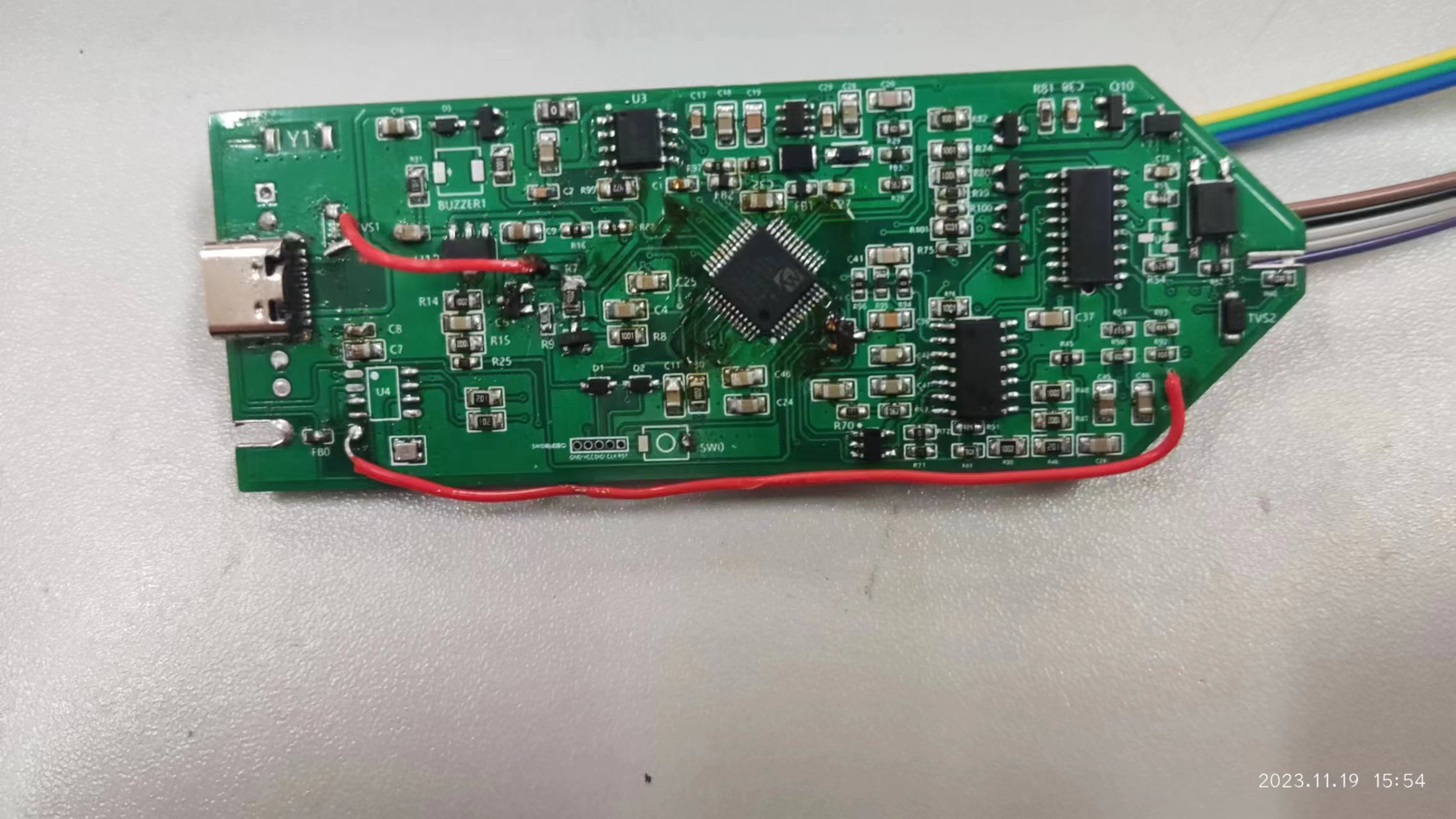
Multifunctional test pen
This multi-functional pen can be used to measure resistance and output PWM waveforms.
A portable multi-functional test pen with voltage measurement, continuity measurement, diode detection, and signal output functions was built based on the CW32F030.
This pen is a minor modification of the official design.
1. Main controller: CW32F030C8T6
; 2. Charging circuit:
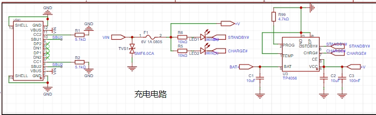
This multi-functional pen uses a TP4056 power management chip to charge the battery (the official solution uses TP4057)
. Since there are many TP4056 power management chips available, the TP4057 was not used;
3. Power supply for the analog section;
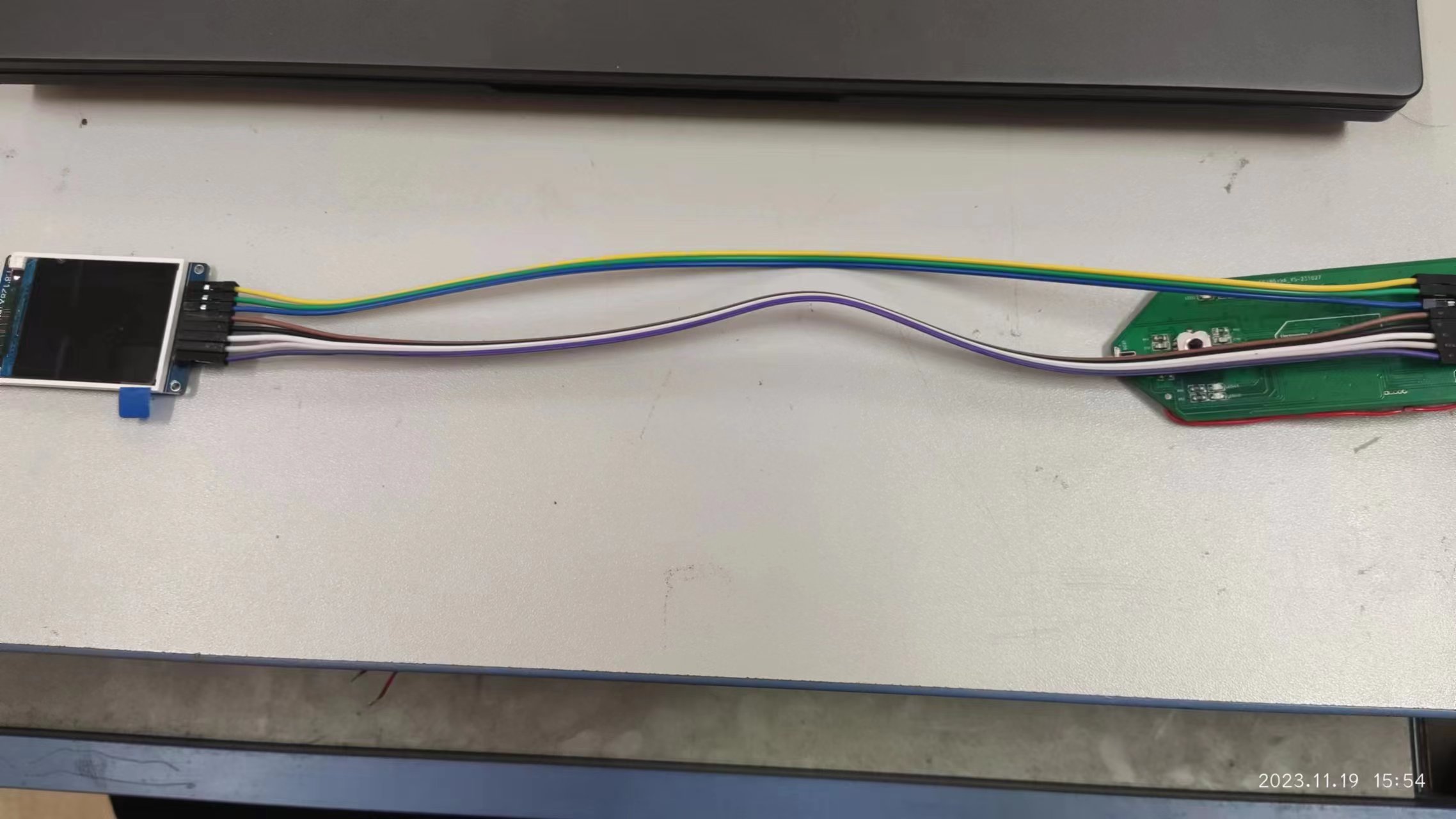
4. Schematic diagram

(front and
back) .
Gerber_PCB1_2023-11-17.zip
CW32 Pen Schematic Diagram.pdf
PDF_Multifunctional Test Pen.zip
Altium Multi-functional Test Pen.zip
PADS_Multifunctional Test Pen.zip
BOM_Multifunctional Testing Pen.xlsx
97141
electronic


 京公网安备 11010802033920号

 SC2128A-D30D


