Working principle and characteristics of electromagnetic relays, selection method of rated working voltage of relays
Source: InternetPublisher:黄土马家 Keywords: Relay Automatic switch Electromagnetic relay Updated: 2025/03/04
Relay is an automatic switch element with isolation function. It is widely used in remote control, telemetry, communication, automatic control, mechatronics and power equipment. It is one of the most important control elements. Relay is actually an "automatic switch" that uses a smaller current to control a larger current. Therefore, it plays the role of automatic adjustment, safety protection, and circuit conversion in the circuit.
Relay characteristics of relay:
When the input signal x of the relay increases continuously from zero to the action value xx when the armature begins to attract, the output signal of the relay immediately
jumps from y=0 to y=ym, that is, the normally open contact changes from off to on. Once the contact is closed, the input quantity x continues to increase, and the output signal y will no longer change. When the input quantity x
drops from a value greater than xx to xf, the relay begins to release and the normally open contact is disconnected. We call this characteristic of the relay the relay characteristic, also called the input-output characteristic of the relay.
1. Working principle and characteristics of relay
1. Working principle and characteristics of electromagnetic relay
Electromagnetic relays are generally composed of an iron core, a coil, an armature, a contact reed, etc.
As long as a certain voltage is applied to both ends of the coil, a certain current will flow through the coil, thereby generating an electromagnetic effect. The armature will overcome the pulling force of the return spring under the action of electromagnetic force and be attracted to the iron core, thereby driving the moving contact of the armature and the static contact (normally open contact) to close.
When the coil is powered off, the electromagnetic attraction disappears, and the armature returns to its original position under the reaction force of the spring, releasing the moving contact and the original static contact (normally closed contact). In this way, the purpose of conducting and cutting off in the circuit is achieved through attraction and release.
The "normally open and normally closed" contacts of the relay can be distinguished as follows: the static contact that is in the disconnected state when the relay coil is not energized is called the "normally open contact"; the static contact that is in the connected state is called the "normally closed contact".
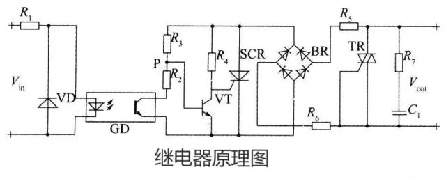
2. Circuit principle
2.1 Brief Introduction of Relay
A relay is a device whose contacts (or circuits) connect or disconnect small-capacity AC or DC control circuits when the input quantity changes to a certain value.
2.2 Working Principle
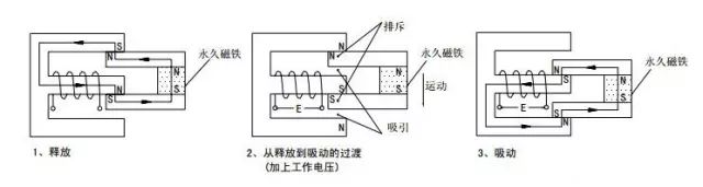
The permanent magnet maintains the released state. When the working voltage is applied, electromagnetic induction causes the armature and the permanent magnet to produce attraction and repulsion torques, resulting in downward movement, and finally reaching the attracted state.
3. Transistor drive circuit
3.1 Circuit Schematic Diagram
When a transistor is used to drive a relay, an NPN transistor is recommended.
The specific circuit is as follows:
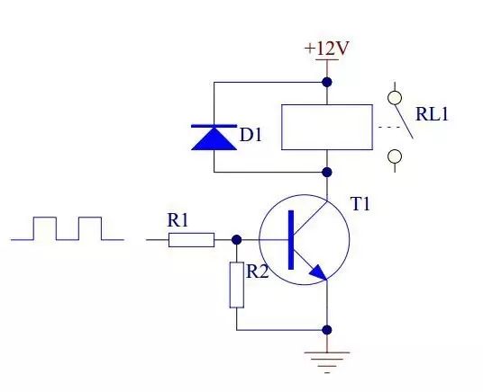
When the input is high level, transistor T1 is saturated and turned on, the relay coil is energized, and the contacts are closed. When the input is low level, transistor T1 is cut off, the relay coil is de-energized, and the contacts are opened.
3.2 The role of each component in the circuit
(1) Transistor T1 is the control switch.
(2) Resistor R1 mainly plays a current limiting role, reducing the power consumption of transistor T1.
(3) Resistor R2 ensures that transistor T1 is reliably cut off.
(4) Diode D1 provides reverse freewheeling current, providing a discharge path for the relay coil when the transistor turns from on to off, and clamps its voltage at +12V.
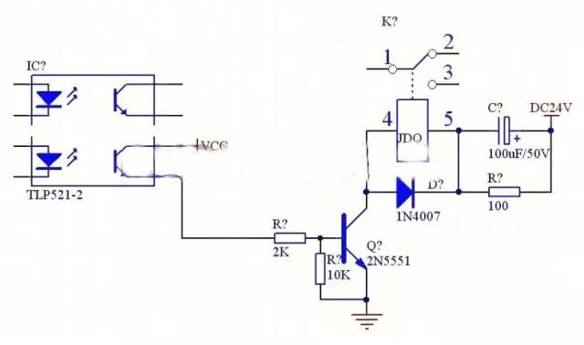
4. Integrated circuit drive circuit
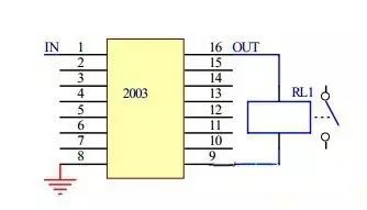
Currently, integrated circuits that integrate multiple drive transistors are used. Using such integrated circuits can simplify the design process of a printed circuit board that drives multiple relays.
When the input terminal of 2003 is at a high level, the corresponding output port outputs a low level, the two ends of the relay coil are energized, and the relay contacts are energized; when the input terminal of 2003 is at a low level, the corresponding output port is in a high-impedance state, the two ends of the relay coil are de-energized, and the relay contacts are disconnected.
24V relay drive circuit:
Relay series RC circuit:
This form is mainly used in circuits where the rated working voltage of the relay is lower than the power supply voltage. When the circuit is closed, the relay coil will generate an electromotive force due to self-inductance, which will hinder the increase of current in the coil, thereby extending the pull-in time. The pull-in time can be shortened by connecting the RC circuit in series.
The principle is that at the moment the circuit is closed, the voltage across the capacitor C cannot change suddenly and can be regarded as a short circuit. In this way, a power supply voltage higher than the rated working voltage of the relay coil is added to the coil, thereby accelerating the speed at which the current in the coil increases and causing the relay to close quickly. After the power supply is stable, the capacitor C does not work and the resistor R plays a current limiting role.
2. Selection of rated working voltage of relay
The rated working voltage of the relay is the most important technical parameter of the relay.
When using a relay, the operating voltage of the circuit (that is, the circuit where the relay coil is located) should be considered first. The rated operating voltage of the relay should be equal to the operating voltage of the circuit.
Generally, the working voltage of the circuit is 0.86 of the rated working voltage of the relay. Note that the working voltage of the circuit must not exceed the rated working voltage of the relay, otherwise the relay coil will easily burn out.
In addition, some integrated circuits, such as NE555 circuits, can directly drive relays to work, while some integrated circuits, such as COMS
circuits, have a small output current and require a transistor amplifier circuit to drive the relay. In this case, it should be considered that the transistor output current should be greater than the rated working current of the relay.
When a transistor is used to drive a relay, the emitter of the transistor must be grounded. The specific circuit is as follows:
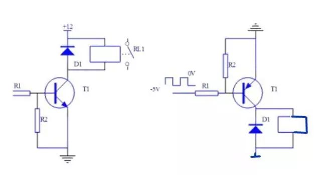
When driving NPN transistor:
When a high level is input to the base of transistor T1, the transistor is saturated and turned on, and the collector becomes a low level, so the relay coil is energized and the contact RL1 is closed.
When a low level is input to the base of transistor T1, the transistor is turned off, the relay coil is de-energized, and the contact RL1 is opened.
- A simple magnetic switch circuit sharing
- How to choose the right level of integration to meet motor design requirements?
- Use your smartphone to turn on/off the power in your home
- How to build a simple tachometer using an infrared reflectance sensor
- A small improvement to the temperature and water level indicator alarm
- One-way rotation circuit of motor controlled by contactor
- Hydraulic control circuit design and analysis
- Design and analysis of touch delay switch circuit composed of CD4011 and CD4001
- Motorcycle anti-theft device circuit design
- Homemade short circuit alarm device
- Differential amplifier emitter negative feedback gain control circuit
- Stapler control circuit
- Chandelier control circuit
- Neon light control circuit
- Water dispenser (Aucma) temperature detection control circuit
- Control circuit of Gao Shida 25860T microwave oven turntable assembly
- Forward and reverse control circuit of micro DC motor a
- audio signal control circuit
- Inverter brightness control circuit
- Apply LOGO! Electric gate control circuit b


 京公网安备 11010802033920号