What does the power battery BMS functional safety development process include?
Source: InternetPublisher:萌面大虾 Keywords: Power battery bms Updated: 2025/02/28
1. Definition of functional safety
There is no unreasonable danger caused by failure of electrical and electronic systems. Therefore, the first priority of functional safety development is to avoid unacceptable risks. As a vehicle component, BMS generally obtains FSR (functional safety requirements) from the safety goals at the vehicle level during the concept stage when developing functional safety. Then, the TSR (technical safety requirements) at the electrical and electronic level is analyzed from the FSR at the concept stage. Finally, the functional safety requirements of the bare metal server hardware and software are analyzed.
Overview
In the ISO26262 standard, we need to distinguish between two types of failures and errors: random failures and systematic failures. Systematic failures can be avoided by appropriate methods during the design phase, while random failures can only be reduced to an acceptable level. Systematic or even random failures can occur in hardware, while software failures are more systematic failures. First, based on the safety goals, determine the safety level. For each hazardous event, determine its ASIL level based on the three elements of exposure probability E, controllability C, and severity S.
According to the development process of ISO26262, starting from the demand, including conceptual design, system design, hardware design, software design, until the final production release and after-sales maintenance, the corresponding functional safety requirements are put forward. It covers the entire life cycle of the car, thereby ensuring the safety and reliability of the functions of automotive electronic products, and even if the function fails, it will not cause danger. As the key to new energy vehicles, the functional requirements of BMS are becoming more and more complex. BMS must have basic sampling functions such as voltage, current and temperature. At the same time, it can monitor the operation of the battery in real time and provide protection functions such as overvoltage, undervoltage, overcurrent, and overtemperature. As well as predictions such as SOP, SOC, SOH, fault diagnosis, balance control, thermal management, fast and slow charging management. Applying the requirements of the ISO26262 standard to the development of BMS will greatly improve the safety of BMS.
ISO26262 quality management system certification
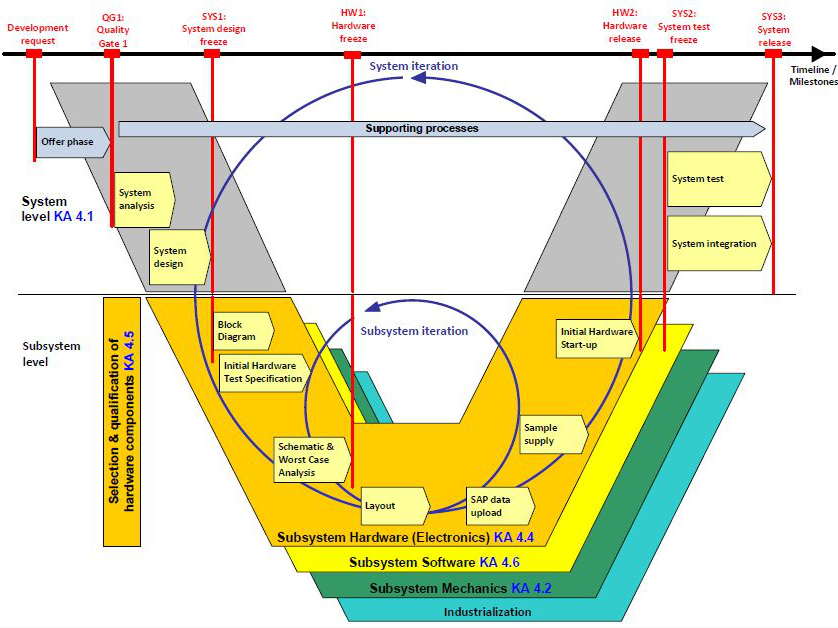
If the BMS is considered as a safety element out of context (independent safety unit), the meaning of the independent safety unit is that other elements in the vehicle are temporarily not considered in the product development cycle. According to the safety goals provided by the OEM, BMS developers and suppliers derive safety requirements based on the safety goals, followed by system design, hardware design, software design, etc. As part of the whole vehicle, some functions on the whole vehicle will interact with the battery system, and the results of their effects must be considered from the perspective of related projects. BMS is developed based on the development practice of automotive electronics and the main processes of the V-type, and the OEM will participate in the testing part on the right side of the V-type.
3. Definition of relevant terms
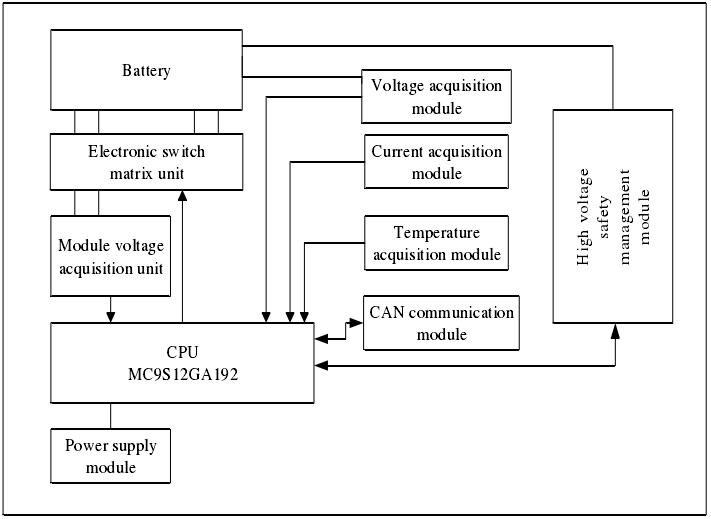
The battery high voltage system is mainly composed of junction boxes, modules, battery equalization connectors, high voltage connector modules, and BMS. BMS collects data such as voltage and temperature through sensors for processing, calculates the SOC/SOH of the battery, and diagnoses faults. At the same time, information is exchanged with the VCU through the vehicle CAN. When defining related projects, it is necessary to analyze the components of the battery system and define the scope of the functional safety analysis. The figure below is a structural and principle block diagram of the battery system. The functional safety goals undertaken by BMS are achieved at the vehicle-related project level. On this basis, the development and verification of BMS products are carried out.
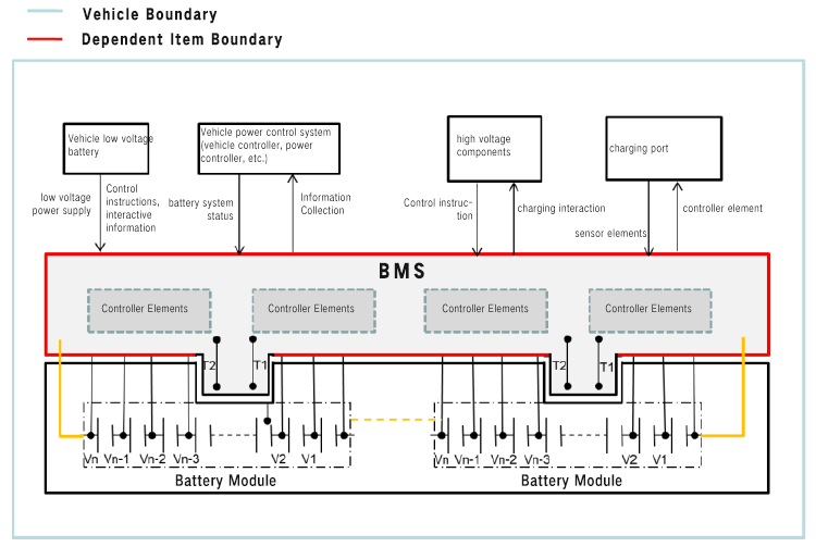
Vehicle Boundary
4. The development process starts with identifying dangerous events
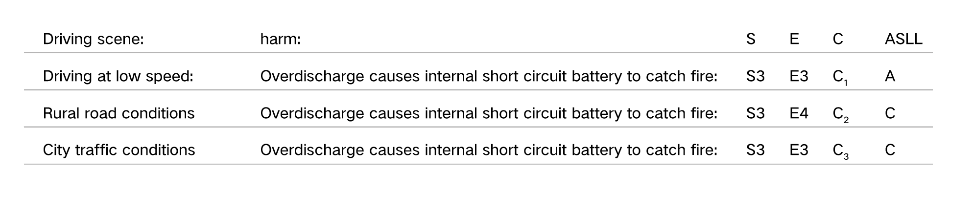
According to different working conditions, different driving habits, and weather conditions, analyze the high-probability dangerous events and assign the dangerous events to various functional departments of the system. In ISO26262-3, Hazrad analysis can be confirmed by brainstorming, DFMEA, and other methods. Taking the dangerous event of overcharging of a single battery as an example, the level of the dangerous event is determined according to the three elements of the ASIL level. The following table is a simple HARA analysis of battery overcharging. In this table, if the thermal runaway of the battery cell causes the vehicle to catch fire on an urban road, the ASIL level is set to C; when the vehicle is at a relatively low speed, the ASIL level is set to A. List all possibilities of functional failure due to failure;
Summarize all functions and faults, differentiate them according to the operation mode, and form a dangerous event matrix. Define the functional safety goals of dangerous events through hazard analysis and risk assessment. Combine the safety levels of the same dangerous event in different scenarios, and use the highest functional safety level as the safety level of the dangerous event. This will avoid the occurrence of dangerous events and form safety goals.
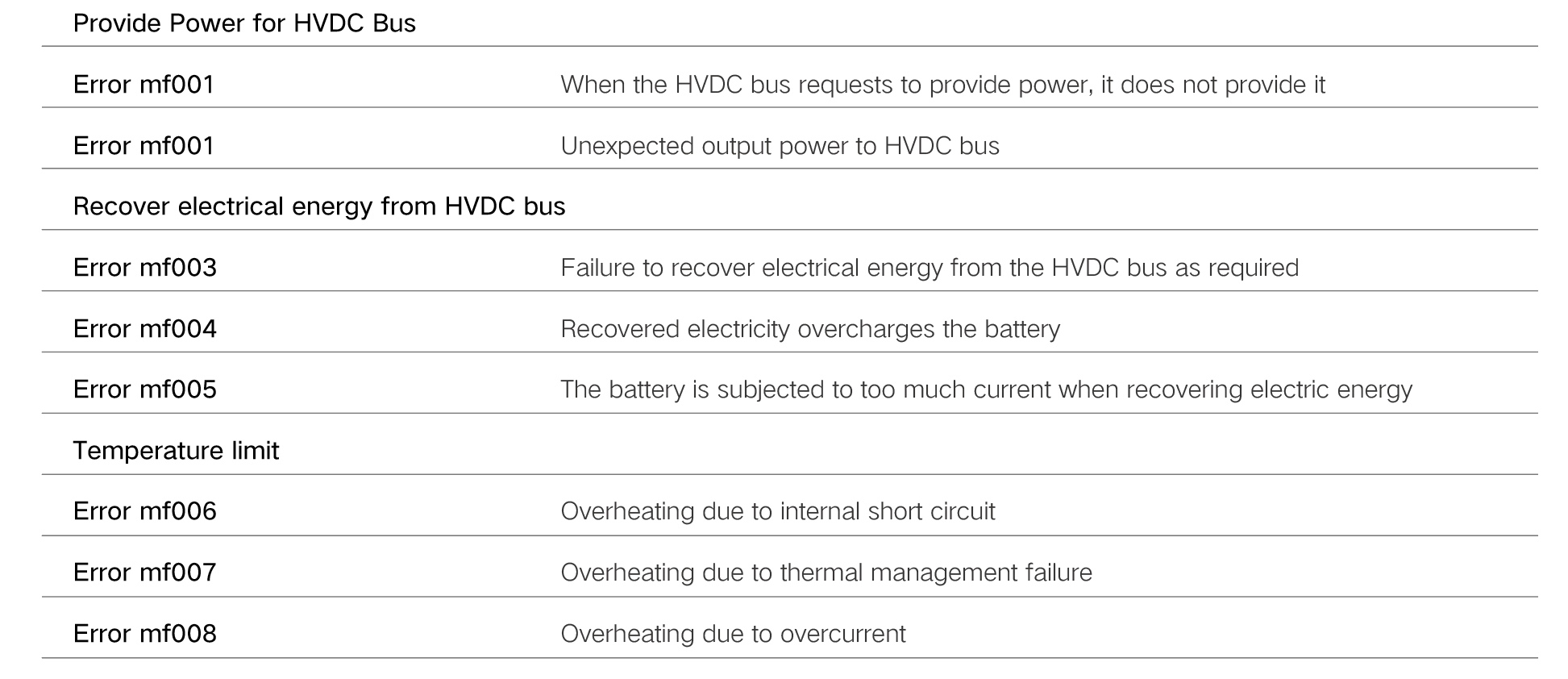
Safety goals can be considered from the perspective of avoiding dangerous events, or from the perspective of avoiding failures. For example, a safety goal is proposed to prevent the danger of internal battery short circuit fire caused by over-discharge. Safety goals are proposed from the perspective of avoiding danger to prevent battery short circuit fire caused by over-discharge, and safety goals are proposed from the perspective of avoiding failure and avoiding temperature limit failure. The ASIL level of the safety goal is the highest level of dangerous events. The derivation of safety goals and some derived safety-related parameters also need to be specified. These parameters include: working mode, fault tolerance time, safety state, functional redundancy,
The second step is to determine the functional safety requirements of the FSRs. Each safety goal defines at least one functional safety requirement. Although a functional safety requirement can cover multiple safety goals, each FSR inherits the highest ASIL from the associated SG. With a layered approach, the safety goals are derived from risk assessment and hazard analysis, and the functional safety requirements are derived from the safety goals. The functional safety level of the FSR automatically inherits the highest level of the safety goal.
Description: To prevent the battery from catching fire due to internal short circuit caused by over-discharge, the current should be cut off when over-discharge is detected.
5. Extract Technical Safety Requirements (TSR) from Functional Safety Requirements (FSR)
Throughout the development life cycle, technical safety requirements are technical requirements for implementing the concept of functional safety. The intention is to move from detailed single-level functional safety requirements to system-level safety technical requirements. The following table is an example of converting functional safety requirements into technical safety requirements, for process reference only.
Development Lifecycle
The fourth step is the system design phase. The system and subsystem need to implement the above technical safety requirements and need to reflect the safety detection and safety mechanisms defined above. Technical safety requirements should be assigned to system design elements, and the system design should complete the technical safety requirements. Regarding the implementation of technical safety requirements, the following issues should be considered in system design, defining the system architecture, assigning TSRs to hardware and software, and defining the hardware-software interface HIS. The hardware and software interface specifications should clarify the interaction between hardware and software and be consistent with the concept of technical safety, and should include components of hardware devices that are controlled by software and hardware resources to support the operation of the software. For system design, three principles are given in the standard: modularity, appropriate granularity, and simplicity. For different security levels, it emphasizes different aspects of design considerations.
5. Hardware system functional safety design
The detailed safety requirements for hardware come from TSR, system architecture, and system boundary HSI. According to ISO6-4 hardware safety requirements Chapter 2.26262.8, the specification should include all safety-related hardware requirements, and the hardware safety requirements should be verified in accordance with the requirements of ISO6-9 Chapter 26262 and Chapter 8 to provide evidence. The hardware design can start with the hardware functional block diagram, and all elements and internal interfaces of the hardware block diagram should be shown. Then design and verify the detailed circuit diagram, and finally verify the possible faults of the hardware architecture through methods such as deductive method (FTA) or inductive method (FMEA). For the BMS system, the battery pack voltage sensor is a very important sensor, so it is necessary to analyze the different failure modes of the battery pack voltage sensor for different ASIL levels. Some failure modes can be prevented by hardware requirements, and some failure modes can be divided into software requirements for prevention.
How to design each technical safety requirement is closely related to the actual product function, technology development level, supplier level, etc., and is the starting point for product differentiation among different manufacturers. The specific implementation of products has its own ideas. Some do not apply safety mechanisms and directly require components to improve their own functional safety levels; some choose to add monitoring mechanisms or provide redundant designs with different principles to improve the functional safety level.
7. Software system design
Software development in the automotive industry generally follows the V model, with the development process on the left and the corresponding testing process on the right. The BMS software development process is basically consistent with the V model of the software development process recommended in Part 6 of ISO26262, as shown in the figure below. In software architecture design, attention should be paid to the maintainability and testability of the software. In the automotive industry, software should consider the maintainability of the entire product cycle, while considering the difficulty of designing and testing the software architecture. In the ISO26262 standard, testing is a very important aspect, and any design should also consider the convenience of testing. At this point, the design and development of this product has been completed.
The software architecture design principles recommended by this standard are as follows:
method
ASIL Level
Hierarchy of software components
Limit the size of software components
Limiting the size of an interface
High cohesion within each component
Loose coupling between software components
Properties of Correct Scheduling
Limit the use of interrupts
The “limited” in methods 1b, 1c, and 1g represent minimum levels, balanced with other design considerations
For example, approaches 1d and 1e can be implemented through separation of concerns, which represent the ability to identify, package, and operate on parts of the software that are related to a specific idea, goal, task, or purpose.
Method 1e Limit external coupling of software components Any interrupts used should be based on priority
The error handling mechanism recommended by the software architecture level standard is as follows:
Static recovery mechanism
Moderate downgrade
Independent parallel redundancy
Data Error Correction Code
Static recovery mechanisms may include recovery using recovery blocks, backward recovery, forward recovery, and recovery from backup.
Graceful degradation of software levels refers to the prioritization of different functions to minimize the adverse effects of potential failures on functional safety.
Independent parallel redundancy can be achieved by different software in each parallel path.
- Detailed explanation of the working principle of the parking light circuit
- DIY a practical audio-visual doorbell
- Battery equalization system and control method thereof
- UCC587x-Q1 power-on false alarm mechanism and initialization precautions
- What components and functions does the battery management system consist of?
- One control three constant pressure water supply frequency conversion speed control circuit a
- Gantry milling machine spindle control circuit
- Electric massager circuit
- Slow logic pulse listener circuit diagram
- Cadillac reversing light circuit diagram


 京公网安备 11010802033920号