Working principle of filter capacitors, importance of capacitor filters in bridge rectifier circuits
Source: InternetPublisher:笑流年 Keywords: Capacitors Bridge Rectifiers Filter Capacitors Updated: 2025/02/18
In the process of developing microcontroller solutions, it is often necessary to select a suitable filter capacitor. Of course, the filter capacitor is one of the basic types of capacitors, and it is designed in a way that prevents a certain range of frequency signals from entering another circuit. It is very advantageous during the filtering of low-frequency signals. Therefore, capacitors are usually used as parallel plate capacitors. In general, capacitors are connected to the corresponding circuits so that the desired signal is filtered and the excess signal is eliminated from the circuit. This capacitor has many applications in signal suppression, circuits to eliminate burrs, etc.
What is a filter capacitor?
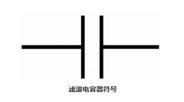
Definition: Capacitors that are used to filter certain desired frequency signals can be defined as filter capacitors. Filter capacitors can be designed to pass low frequency signals or high frequency signals or even certain types of signals can be filtered by these types of capacitors. The filter capacitor symbol is shown below.
Usually a basic parallel plate capacitor. But its connection to the circuit makes it different. Sometimes, ceramic capacitors are also preferred for limiting signals.
Working principle of filter capacitor
The capacitor works according to a principle called capacitive reactance. Capacitive reactance means that the impedance value of a particular capacitor changes depending on the frequency signal passing through the corresponding capacitor. Let us consider the example of a resistor in a circuit. The resistance of a device cannot be changed, it provides the same resistance based on its fixed value. But a capacitor has a variable capacitance. The capacitance is affected by the frequency value of the signal applied.
Therefore, these devices are known as reactive devices. Since this type of capacitor participates in the circuit, the impedance value changes. If the value of the frequency signal is high, then in this case, the resistance provided by this particular capacitor is low and vice versa. Hence, this shows that the resistance and frequency of the signal are inversely proportional to each other.
Filter capacitor
The filter capacitance can be derived based on the cut-off frequency selected for filtering and the frequency variation of the impedance dependent signal.
Xc = 1/2 * 3.14 * fc
The above formula shows the inverse relationship between the cutoff frequency of each circuit and the change of each impedance in the circuit.
Filter capacitor circuits block direct current and pass alternating current
As already discussed, it provides low resistance with respect to high frequency signals and high resistance with respect to low frequency signals. In order to block DC, we need to send high frequency signals preferentially. In this case, the designed circuit acts as a high pass filter.
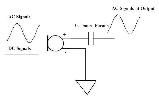
But in some cases, the circuit requires both DC and AC signals. The best example in this case is the use of a microphone. This requires an initial current as DC to start the circuit. After that, AC signals are sent and received at the output. About 0.1 microfarad value of the capacitor is chosen in the circuit so that it can block the DC value, and the AC signal passes through the circuit.
Application Areas
This type of capacitor is very beneficial in various circuits. Listed below are some of the applications of filter capacitors:
1. When designing analog filters such as high-pass filters and low-pass filters.
2. Line filters in TV sets can prevent image flickering.
3. As a protection circuit, such as air conditioners, refrigerators, etc.
4.These are mainly preferred in signal processing.
Filter capacitors have many applications in various fields, let us see the importance of capacitor filters in bridge rectifier circuits.
Bridge Rectifier
Generally, a full wave rectifier can be plotted to get a smooth value of Dc as output compared to the output of a half wave rectifier. However, the output of this rectifier still consists of certain ripples in the circuit. Therefore, in order to remove these ripples, a filtering circuit is connected to the bridge rectifier. This helps in getting the resulting output in the form of pure DC.
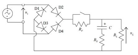
Unwanted pulsed AC can be eliminated by capacitors. Hence, capacitor filters have many applications as ripples in circuits can be eliminated.
- Improved high gain amplifier circuit
- Low noise instrument amplifier circuit
- 50Ω input-output impedance 16dB wideband video amplifier circuit
- Harmonic-free transmitter circuits for frequencies up to 200 MHZ
- Differential input-differential output circuit
- 250mA high speed buffer BUF634
- Amplifier for measuring tiny currents
- Broadband High-Z Buffer
- lW transmitter circuit with frequency range of 16MHz
- Photoelectric isolation feedback amplifier TPS5904 application circuit
- Autotransformer schematic diagram
- Constant voltage and constant current control circuit diagram composed of current amplifier
- Circuit engineers, master these 15 basic analog circuits before starting!
- Various secondary circuit diagrams and their explanations
- Typical Schmitt trigger circuit diagram
- Incandescent lamp dimming circuit
- 24h automatic switching capacitor control circuit
- W7800 series application circuit
- Power circuit with smoothing filter capacitor
- Police car sound and light analog circuit


 京公网安备 11010802033920号