Two-wire I2C Arduino LCD display
Source: InternetPublisher:z6HnSmwHu Keywords: Arduino LCD display I2C Updated: 2026/01/06
Dual-line I2C Arduino LCD Display
In this tutorial, you will learn how to build a simple serial 16x2 LCD display controlled via an Arduino board using only two wires. The underlying principle is implemented using the PCF8574 chip, an I/O expander that communicates with a microcontroller using the I2C protocol. The PCF8574 is a quick and easy solution for expanding and adding output/input ports to an Arduino. This chip connects to the standard I2C bus and adds eight additional output ports. A total of eight LCD displays can be connected to the same two-wire I2C bus, each with a different address.
First, you must download the library; there are different downloads available for Arduino versions 1.0 and 0022:
Arduino 1.0 libraries
Libraries for Arduino 0022 and earlier versions
Next, extract the files to the libraries folder in your Arduino installation directory.
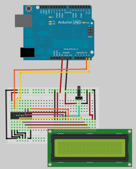
Prepare your breadboard and build the circuit as shown in the first picture.
Open your Arduino IDE, go to File > Examples > LiquidCrystal_I2C and select "Hello World". The following code will open:
#include
#include
`LiquidCrystal_I2C lcd(0x20,16,2);` // Sets the LCD address to 0x20 for 16 characters and 2 lines of display.
`void setup()
{
lcd.init(); // Initializes the LCD
// Prints messages to the LCD.
lcd.backlight();
lcd.print("Hello, world!");
lcd.print("Electronics-DIY.com");
}
void loop()
{
}`
Learn how the PCF8574 works.
The PCF8574 is an 8-bit I/O port expander that uses the I2C protocol. This protocol uses a two-wire serial interface for communication, with one wire for serial clock (SCL) and the other for serial data (SDA). Using this IC, you can control up to eight digital I/O ports using only two ports on your Arduino board. In the I2C protocol, each IC has a unique address; for the PCF8574, you have a 3-bit address, allowing you to connect up to eight devices for a total of 64 ports.
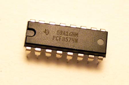
We can view the pinout of the PCF8574 in the datasheet:
Where: A0, A1, and A2 are address pins.
P0, P1, P2, P3, P4, P5, P6, and P7 are digital I/O ports (each is 1 bit).
SDA and SCL are I2C pins for communicating with the microcontroller.
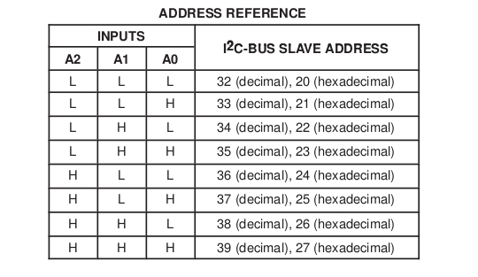
For the IC to function, an address needs to be set; this information can be found in the datasheet.
Where: L represents low level or 0V (GND), H represents high level or VCC
To define the addresses, set A0, A1, and A2 to your desired H or L. Remember that each IC should have a different address.
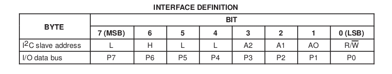
By examining the data interface, we can see how the I2C interface works on the PCF8574:
If you send an I/O data byte, it will turn the corresponding pins P1 through P7 on or off depending on the byte sent. For example, if you send the number 32, it will be binary 00100000, which will only turn on the P5 output. The same applies to reading; if you receive the number 32, it means that only port P5 is open at that time.

- Universal 3V LED flasher
- Simple 300W lamp dimmer
- Fire safety evacuation emergency signs
- DIY a hat with a programmable LED display
- Delayed gradual lighting with protection function
- Design and production of a practical electronic counting device
- Use MC1455PIG to make automatic cycle light-emitting diode circuit
- Infrared detection alarm
- One of the bead-type emergency light circuits
- Infrared remote control dimmer light circuit
- Digital camera on-screen display circuit PCA8515
- LCD backlight power supply circuit
- I2C address switching circuit
- 555 timer disconnection photoelectric isolation safety protection circuit
- Breathing light circuit diagram designed by NE555
- Micromotor pedal speed regulator circuit and improvement
- The battery fast charging circuit is composed of BQ2002 battery fast charging control integrated circuit
- Use 555 to make DC-DC boost circuit


 京公网安备 11010802033920号