Simple coil turns measuring instrument based on 555
Source: InternetPublisher:偷熊计划 Keywords: Measuring instrument Updated: 2025/06/20
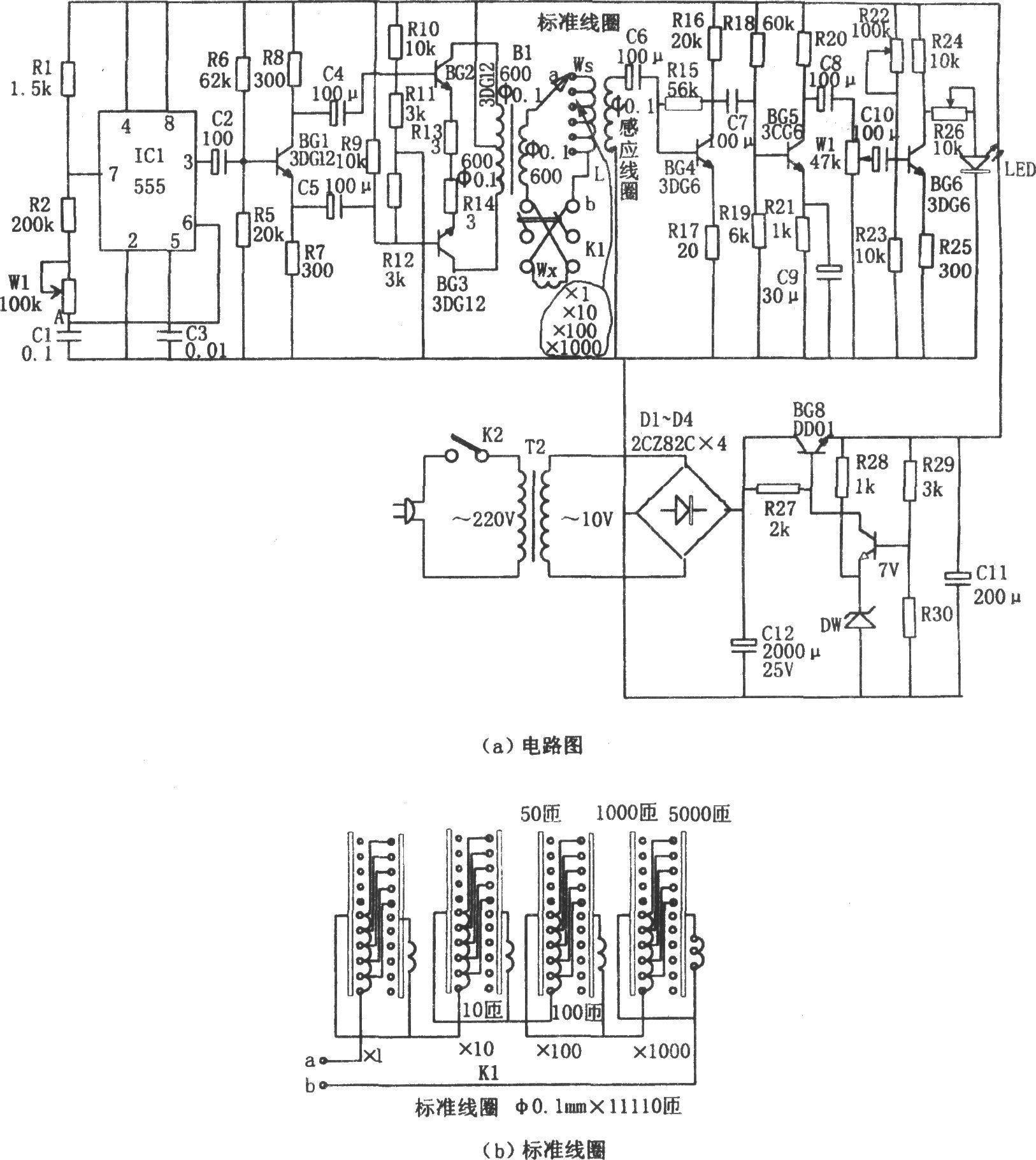
As shown in the figure, this is a simple coil turns measurement circuit. The measuring instrument consists of a pulse signal generator, a driving stage, an inductive receiving part, a light-emitting display part, a step-down power supply, etc.
The measurement of the coil adopts the "magnetic pressure comparison principle", that is, an alternating current I is passed through the coil to be tested Wx and the standard coil Ws. If the two coils are connected in series in reverse phase, their total magnetic motive force is: Vm=(Ws-Wx)i. If Ws=Wx, then Vm=0, and the number of turns of the coil to be tested can be estimated by the number of turns of the known standard coil.
The pulse signal generator is a multivibrator composed of IC1 (555) and R1, R2, W1, C1. Its oscillation frequency is f=1.44/(R1 2R2 2Rw1)C1. The frequency range corresponding to the parameters shown in the figure is: 40~70Hz. Adjust the potentiometer W1 to make it oscillate at 50Hz.
The driving stage is a Class A push-pull amplifier stage composed of BG2, BG3 and B1. The standard coil and the coil to be tested (anti-phase series connection) are connected to the secondary of B1. The signal induced by L is amplified by BG4~BG6. If BG6 has no signal output, the light-emitting diode LED does not emit light, indicating that the number of turns of the standard coil is the same as the number of turns of the coil to be tested, that is, Ws=Wx; if BG6 has a signal output, the LED is always in the light state, which means Ws≠Wx.
This measuring instrument can be used to measure coils of transformers, instruments, motors, etc., and is suitable for coils of any geometric shape. The measuring range is 1 to 11110 turns, and the measuring accuracy is ±2%. When measuring, the number of turns of the coil to be measured should be estimated in advance, and different gears should be selected. If the sensitive point cannot be found, the number of turns may be too far apart, or the coil is not reversely connected in series.
- 9V Battery Voltage Monitor
- 30W Digital RF Power Meter
- LC measuring instrument based on AVR microcontroller
- Analog Capacitor ESR Tester
- Achieving higher-accuracy battery fuel gauge performance in ultra-low-power systems
- Design and production of logic detectors
- Homemade inductive AC voltage tester
- Circuit solution for providing constant current load for testing battery
- Analog capacitance measuring instrument composed of CD4013
- Temperature measurement circuit using AD7714
- Printing machine photoelectric paper break detection circuit
- Overcurrent detection circuit
- Three-phase alternating current detection circuit
- Bus door status detection circuit
- Computer power detection circuit
- Light detection circuit with output filter to reduce noise
- Cordless telephone ring current detection circuit
- Combustible gas and toxic gas dual-purpose detection circuit
- Revolution detection circuit
- Object detection circuit


 京公网安备 11010802033920号