Do you know some methods to eliminate ground loop interference?
Source: InternetPublisher:常思一二 Keywords: emc emi ground loop Updated: 2021/06/03
What is ground loop interference? What harm does it have? In the face of ground loops, ground loops often come and go without a trace, leaving only a trace on the oscilloscope. When the electronic device is working normally, it suddenly appears and then disappears.
Ground loop interference is a common interference phenomenon that often occurs between distant devices connected by long cables. The intrinsic reason is the existence of ground loop current. Since ground loop interference is caused by ground loop current, in practice, it is sometimes found that when the safety ground wire of a device is disconnected, the interference disappears. This is because when the ground wire is disconnected, the Ground loop. This phenomenon often occurs in situations where the interference frequency is low. When the interference frequency is high, it does not matter whether the ground wire is short or not.
Causes of ground loop interference 1:
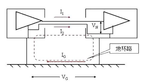
The ground potential of the two devices is different, forming a ground voltage. Driven by this, current flows between the loop formed by device 1 - interconnecting cable - device 2 - ground. Due to the unbalanced nature of the circuit, the current on each wire is different, so differential mode voltage will be generated, causing interference to the circuit. The voltage on the ground wire is caused by the fact that other devices with higher power also use this ground wire, causing a strong current in the ground wire, and the ground wire has a large impedance.
Reason 2 for the formation of ground loop interference:
Since the interconnected equipment is in a strong electromagnetic field, the electromagnetic field induces a loop current in the loop formed by equipment 1 - interconnecting cable - equipment 2 - ground, causing interference in the same process as reason 1.
There are two basic ideas for solving ground loop interference:
One is to reduce the impedance of the ground wire, thereby reducing the interference voltage. The other is to increase the impedance of the ground loop, thereby reducing the ground loop current. When the impedance is infinite, the ground loop is actually cut off, that is, the ground loop is eliminated. For example, floating the device at one end or disconnecting the circuit board from the chassis are direct methods. However, due to electrostatic protection or safety considerations, this direct method is often not allowed in practice. A more practical method is the isolation transformer, optical coupling, common mode choke, balanced circuit and other methods introduced below.
The specific methods are as follows:
1. [Cause of interference]: The "ground potential loop" adds potential voltage division to both ends of the cable shielding layer, and forms a loop through the 75 ohm matching resistors at both ends of the cable, which generates interference voltage on the load.
2. Cut off the ground loop - this is the most effective and simplest method; no anti-interference equipment is needed;
3. One of the anti-interference design principles of the monitoring system is: one end of the terminal monitoring equipment is connected to the earth, and the front-end camera, BNC head shell, and cable shielding layer must be insulated from the earth (open circuit); even if the ground loop interference is suppressed by using anti-interference equipment, It must also be ruled out, because the "ground loop" is changing and unstable. As the number of high-power equipment in the power grid increases and the power imbalance changes, the size of the ground potential difference will also change, and in severe cases, the equipment will be burned. The above is some analysis of ground loop interference. I hope it can help you.
- A very convenient small power supply circuit to share
- In-depth analysis of DC-AC converter inverter
- Practical and convenient fax machine power supply control circuit
- What kind of circuit is a voltage regulator circuit?
- MT3608 constitutes a 3.7V to 12V boost circuit diagram
- INA155/INA156 is used to form a single-supply high-side current monitor for detecting load current
- Driving circuit that controls LED brightness using PWM signal
- Principles and precautions of active discharge circuit
- A simple positive and negative power supply circuit
- Car power 1.5V-12V six-speed converter
- Do you know how to use component layout to improve circuit board EMI?
- Do you understand the management and control of EMI and EMC?
- DC 12V to AC 100V inverter power supply circuit design
- 3v to 5v circuit diagram
- Power circuit of LBO-522 dual trace oscilloscope
- Power circuit with smoothing filter capacitor
- KGDS type single-phase low temperature iron plated power supply circuit
- Recording level power supply circuit
- Household emergency power circuit
- Music power circuit


 京公网安备 11010802033920号