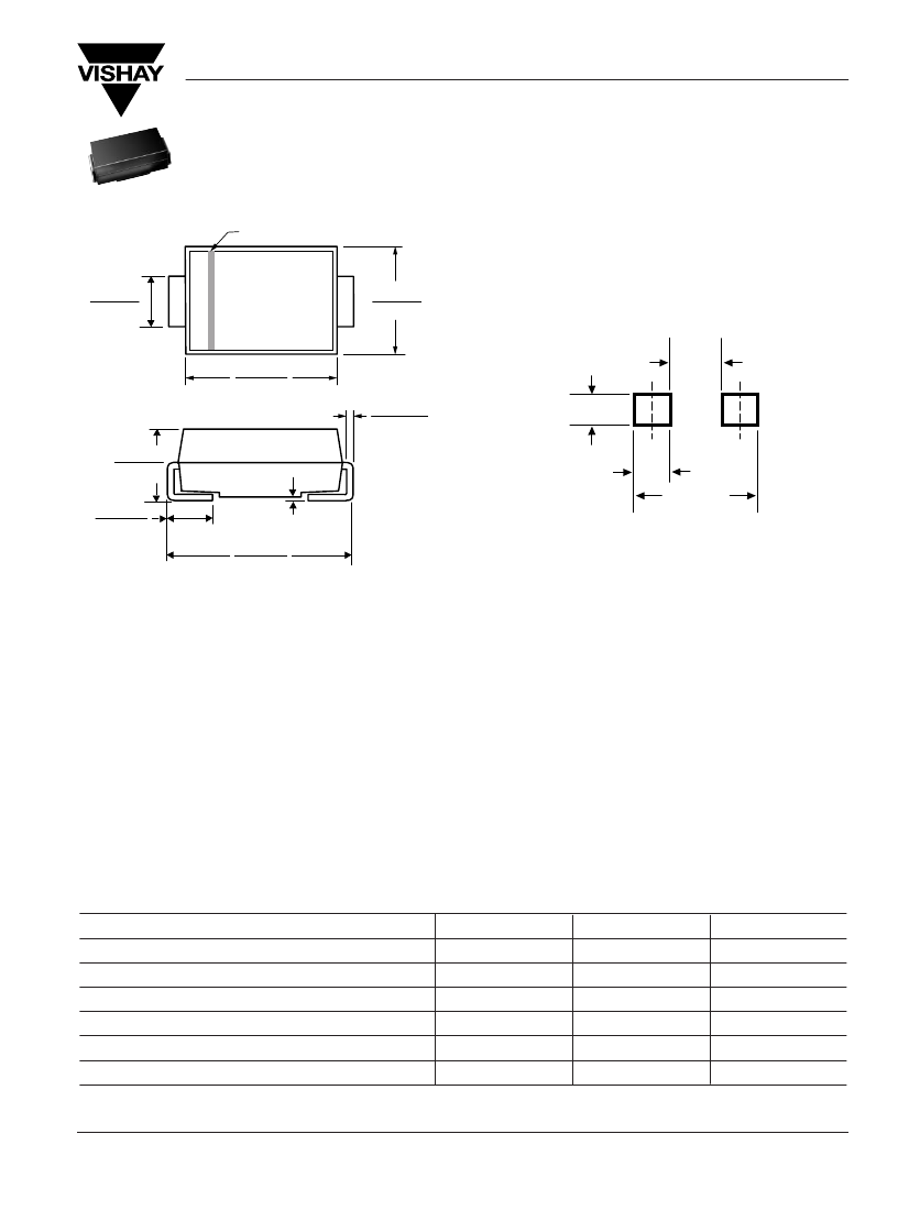
DIODE 10 V, 1.25 W, SILICON, UNIDIRECTIONAL VOLTAGE REGULATOR DIODE, DO-214AC, PLASTIC, SMA, 2 PIN, Voltage Regulator Diode
| Parameter Name | Attribute value |
| Is it lead-free? | Contains lead |
| Is it Rohs certified? | incompatible |
| Maker | Vishay |
| Parts packaging code | DO-214AC |
| package instruction | R-PDSO-C2 |
| Contacts | 2 |
| Reach Compliance Code | unknown |
| ECCN code | EAR99 |
| Configuration | SINGLE |
| Diode component materials | SILICON |
| Diode type | ZENER DIODE |
| Maximum dynamic impedance | 8 Ω |
| JEDEC-95 code | DO-214AC |
| JESD-30 code | R-PDSO-C2 |
| JESD-609 code | e0 |
| Number of components | 1 |
| Number of terminals | 2 |
| Maximum operating temperature | 150 °C |
| Package body material | PLASTIC/EPOXY |
| Package shape | RECTANGULAR |
| Package form | SMALL OUTLINE |
| Peak Reflow Temperature (Celsius) | NOT SPECIFIED |
| polarity | UNIDIRECTIONAL |
| Maximum power dissipation | 1.25 W |
| Certification status | Not Qualified |
| Nominal reference voltage | 10 V |
| surface mount | YES |
| technology | ZENER |
| Terminal surface | TIN LEAD |
| Terminal form | C BEND |
| Terminal location | DUAL |
| Maximum time at peak reflow temperature | NOT SPECIFIED |
| Maximum voltage tolerance | 6% |
| Working test current | 25 mA |
| Base Number Matches | 1 |
 京公网安备 11010802033920号


