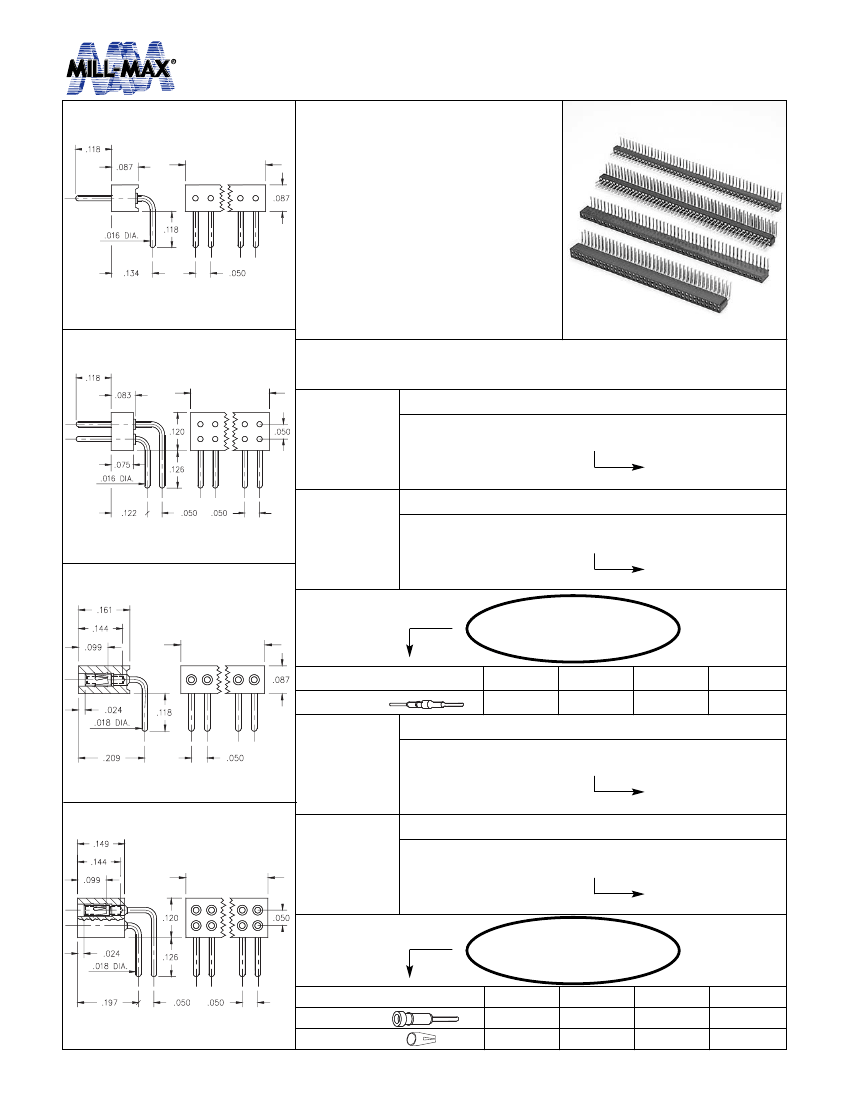
Board Connector, 21 Contact(s), 1 Row(s), Female, Right Angle, Solder Terminal, Socket
| Parameter Name | Attribute value |
| Is it Rohs certified? | incompatible |
| Maker | Mill-Max |
| Reach Compliance Code | compliant |
| Is Samacsys | N |
| Other features | COMPATIBLE CONTACT: 0489-1-15-01-11-02-04-0 |
| Body/casing type | SOCKET |
| Connector type | BOARD CONNECTOR |
| Contact to complete cooperation | TIN LEAD (200) OVER NICKEL |
| Contact completed and terminated | TIN LEAD (200) OVER NICKEL |
| Contact point gender | FEMALE |
| Contact material | NOT SPECIFIED |
| DIN compliance | NO |
| Filter function | NO |
| IEC compliance | NO |
| JESD-609 code | e0 |
| MIL compliance | NO |
| Manufacturer's serial number | 851 |
| Plug information | MULTIPLE MATING PARTS AVAILABLE |
| Mixed contacts | NO |
| Installation method | RIGHT ANGLE |
| Installation type | BOARD |
| Number of rows loaded | 1 |
| Options | GENERAL PURPOSE |
| Terminal pitch | 1.27 mm |
| Termination type | SOLDER |
| Total number of contacts | 21 |
| UL Flammability Code | 94V-0 |
| Base Number Matches | 1 |
 京公网安备 11010802033920号


