F-219
FTE–155–01–G–DV
FTE–120–01–G–DV–A
FTE–130–01–G–DV–ES
(0.80 mm) .0315"
FTE SERIES
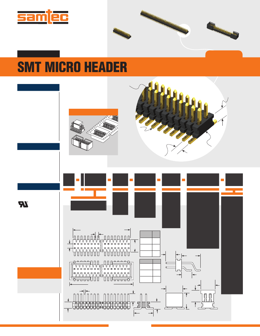
SMT MICRO HEADER
SPECIFICATIONS
For complete specifications and
recommended PCB layouts
see www.samtec.com?FTE
Insulator Material:
Black Liquid Crystal Polymer
Terminal Material:
Phosphor Bronze
Plating:
Au over 50 µ" (1.27 µm) Ni
Current Rating (FTE/CLE):
2.7 A per pin
(2 pins powered)
Operating Temp Range:
-55 °C to +125 °C
RoHS Compliant:
Yes
Mates with:
CLE
Choice of
post heights
Low profile
(1.70 mm)
.067"
OPTIONS
–P OPTION
Surface
Mount
PROCESSING
Lead-Free Solderable:
Yes
-DV Lead Coplanarity:
(0.10 mm) .004" max
-DH Lead Coplanarity:
(0.10 mm) .004" max (05-25)
(0.15 mm) .006" max (26-50)*
*(.004" stencil solution
may be available; contact
IPG@samtec.com)
–ES OPTION
–TR OPTION
Optional
End Shrouds
for blind mating
(0.80 mm) .0315"
micro pitch
FTE
RECOGNITIONS
For complete scope of
recognitions see
www.samtec.com/quality
FILE NO. E111594
NO.
1
PER PINS
ROW
LEAD
STYLE
Specify
LEAD
STYLE
from
chart
PLATING
OPTION
TAIL
OPTION
FLEX SHROUD
OPTIONS
Style –01 –DV only
(11 pins/row min.)
OTHER
OPTION
05 thru 90
= 10 µ"
(0.25 µm)
Gold on post,
Gold flash on
balance
–G
= Dual
Vertical
–DV
= Dual
Horizontal
(50 pos.
max.)
–DH
= End Shroud
–ES
02
No. of positions x (0.80) .0315
(0.80) .0315
180
LEAD
STYLE
A
(1.90)
.075
(4.45)
.175
(3.05)
.120
= End Shroud with
Locking Clips
(Manual placement
required)
–EC
= Alignment
Pin
(5 pos. min.)
Metal or
plastic at
Samtec
discretion
(–DV only)
–A
(3.05)
.120
(1.20)
.047
01
179
–01
–02
–03
OPTION
= End Shroud with
Guide Posts
–EP
A
Z
(1.57)
.062
(4.11)
.162
(5.51)
.217
(5.08)
.200
= (2.50 mm)
.098" DIA
Polyimide
Film Pick &
Place Pad
(–DH only)
= Plastic Pick
& Place Pad
(8 pos. min.)
–DV only
–K
ALSO AVAILABLE
(MOQ Required)
• End shrouds with
board locks
• Gold flash plating
–ES
–EC
No. of positions x
(0.80) .0315 +
Z
(0.30) .012 SQ
–P
–EP
(2.29)
.090
–DH OPTION
(4.17)
.164
(5.08) .200
x
(3.18) .125
= Tape & Reel
Packaging
–TR
A
(1.38)
.055
Note:
Some lengths,
styles and options are
non-standard, non-returnable.
(Shrouded options removed for clarity)
(1.70)
.067
(4.57)
.180
(3.18)
(4.09) .125
.161
–ES OPTION
–P OPTION
Due to technical progress, all designs, specifications and components are subject to change without notice.
All parts within this catalog are built to Samtec’s specifications.
Customer specific requirements must be approved by Samtec and identified in a Samtec customer-specific drawing to apply.
WWW.SAMTEC.COM

 京公网安备 11010802033920号


