F-218 (Rev
10OCT17)
FTR–110–52–G–S
FTR–107–02–G–D–A
(1.27 mm) .050"
FTR–132–52–G–D–P
FTR SERIES
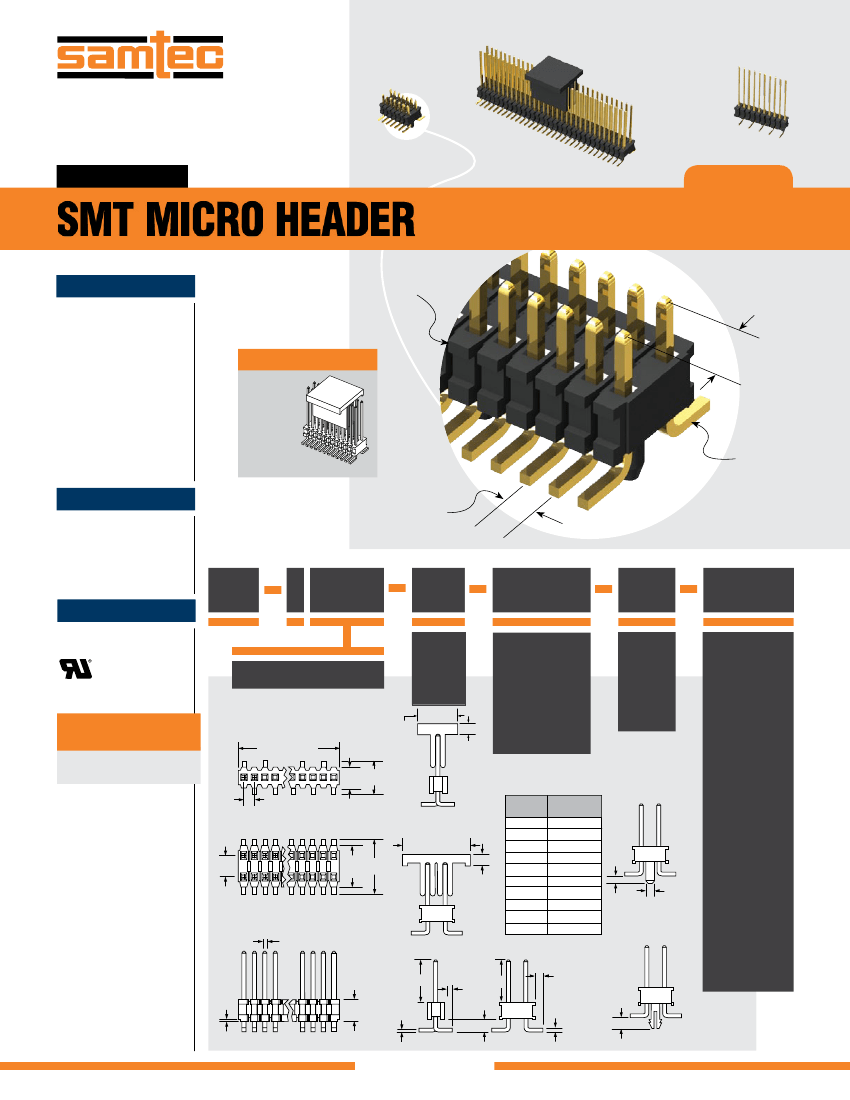
SMT MICRO HEADER
SPECIFICATIONS
For complete specifications and
recommended PCB layouts
see www.samtec.com?FTR
Insulator Material:
Black Liquid Crystal Polymer
Terminal Material:
Phosphor Bronze
Plating:
Au or Sn over
50 µ" (1.27 µm) Ni
Current Rating (FTR/RSM):
3.1 A per pin
(2 pins powered)
Operating Temp Range:
-55 °C to +105 °C with Tin;
-55 °C to +125 °C with Gold
RoHS Compliant:
Yes
Mates with:
RSM, SMS, SLM
Single and
double row
OPTIONS
(2.54 mm)
.100"
–P OPTION
Surface
mount
Available with optional
pick & place pad
PROCESSING
Lead-Free Solderable:
Yes
SMT Lead Coplanarity:
(0.10 mm) .004" max (02-20)
(0.15 mm) .006" max (21-40)*
*(.004" stencil solution
may be available; contact
IPG@samtec.com)
Micro pitch
(1.27 mm) .050"
FTR
1
RECOGNITIONS
For complete scope of
recognitions see
www.samtec.com/quality
FILE NO. E111594
NO. PINS
PER ROW
LEAD
STYLE
Specify
LEAD
STYLE
from
chart
(10.16)
.400
x
(5.08)
.200
PLATING
OPTION
ROW
OPTION
OPTION
02 thru 40
= 10 µ" (0.25 µm)
Gold on post,
Matte Tin on tail
= 10 µ" (0.25 µm)
Gold on post,
Gold flash on tail
–L
= Single
Row
–S
= Polarized
= Alignment Pin
(5 positions
minimum –D only)
(Metal or plastic at
Samtec discretion)
(N/A with -LC)
= Locking Clip
(6 positions
minimum –D only)
(N/A with -A)
(Manual placement
required)
–“XX”
–A
–G
ALSO AVAILABLE
(MOQ Required)
• Other platings
Contact Samtec.
40
= Double
Row
–D
(1.27) .050 x
No. of Positions
01
(1.27)
.050
(2.48)(5.03)
.098 .198
(1.27)
.050 TYP
02
80
–LC
–P OPTION
(9.53) (9.91)
.375 x .390
(4.98) (7.52)
.196 .296
LEAD
STYLE
–01
–02
–03
–51
–52
–53
–54
–55
–56
–57
B
(5.84) .230
(2.54) .100
(3.18) .125
(4.83) .190
(5.21) .205
(7.24) .285
(8.51) .335
(9.91) .390
(10.29) .405
(10.92) .430
(2.54)
.100
01
79
(1.02)
.040
(1.09)
.043 DIA
(1.27)
.050
–A OPTION
(0.46)
.018
SQ
= Plastic Pick
& Place Pad
(–D = 5 positions
minimum)
(–S = 8 positions
minimum)
= Tape & Reel
(–S = 4 positions
minimum)
–P
–P OPTION
(1.27)
.050
(1.27)
.050
(1.27)
.050
(0.46)
.018
SQ
(1.40)
.055
–TR
B
(0.51)
.020
(2.54)
.100
(0.46)
.018
SQ
B
Note:
Some sizes, styles and
options are non-standard,
non-returnable.
–S OPTION
–D OPTION
–LC OPTION
Due to technical progress, all designs, specifications and components are subject to change without notice.
All parts within this catalog are built to Samtec’s specifications.
Customer specific requirements must be approved by Samtec and identified in a Samtec customer-specific drawing to apply.
WWW.SAMTEC.COM

 京公网安备 11010802033920号


