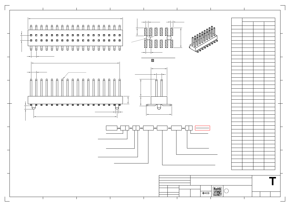
EEWORLDEEWORLDEEWORLD

Part Number

Search

BC050-32A-A1-0380-0160-0480-LD

Description
Board Connector, 32 Contact(s), 2 Row(s), Male, Straight, 0.039 inch Pitch, Surface Mount Terminal, Black Insulator,
CategoryThe connector    The connector   
File Size165KB,1 Pages
ManufacturerGlobal Connector Technology
Environmental Compliance
Download Datasheet Parametric View All

BC050-32A-A1-0380-0160-0480-LD Overview

Board Connector, 32 Contact(s), 2 Row(s), Male, Straight, 0.039 inch Pitch, Surface Mount Terminal, Black Insulator,

BC050-32A-A1-0380-0160-0480-LD Parametric

Parameter NameAttribute value
Is it Rohs certified?conform to
Reach Compliance Codecompli
ECCN codeEAR99
Board mount optionsPEG
body width0.122 inch
subject depth0.063 inch
body length0.63 inch
Connector typeBOARD CONNECTOR
Contact to complete cooperationGOLD FLASH
Contact completed and terminatedGold (Au) - with Nickel (Ni) barrie
Contact point genderMALE
Contact materialCOPPER ALLOY
contact modeRECTANGULAR
Contact resistance20 mΩ
Contact styleSQ PIN-SKT
DIN complianceNO
Dielectric withstand voltage300VAC V
Durability100 Cycles
Filter functionNO
IEC complianceNO
Insulation resistance1000000000 Ω
Insulator colorBLACK
insulator materialLIQUID CRYSTAL POLYMER (LCP)
JESD-609 codee4
MIL complianceNO
Plug contact pitch0.039 inch
Match contact row spacing0.039 inch
Plug informationMULTIPLE MATING PARTS AVAILABLE
Mixed contactsNO
Installation methodSTRAIGHT
Installation typeBOARD
Number of connectorsONE
PCB row number2
Number of rows loaded2
Maximum operating temperature105 °C
Minimum operating temperature-40 °C
OptionsGENERAL PURPOSE
PCB contact patternRECTANGULAR
PCB contact row spacing4.2926 mm
Plating thicknessFLASH inch
Rated current (signal)1 A
GuidelineUL
reliabilityCOMMERCIAL
Terminal pitch1 mm
Termination typeSURFACE MOUNT
Total number of contacts32
UL Flammability Code94V-0
Base Number Matches1
B±0.35
H
1.50
0.50
0.50
Number of
Contacts
4
6
DImensions
A
1.00
2.00
3.00
4.00
5.00
6.00
7.00
8.00
9.00
10.00
11.00
12.00
13.00
14.00
15.00
16.00
17.00
18.00
19.00
20.00
21.00
22.00
23.00
24.00
25.00
26.00
27.00
28.00
29.00
30.00
31.00
32.00
33.00
34.00
35.00
36.00
37.00
38.00
39.00
B
2.00
3.00
4.00
5.00
6.00
7.00
8.00
9.00
10.00
11.00
12.00
13.00
14.00
15.00
16.00
17.00
18.00
19.00
20.00
21.00
22.00
23.00
24.00
25.00
26.00
27.00
28.00
29.00
30.00
31.00
32.00
33.00
34.00
35.00
36.00
37.00
38.00
39.00
40.00
C
---
---
---
3.00
4.00
5.00
6.00
7.00
8.00
9.00
10.00
11.00
12.00
13.00
14.00
15.00
16.00
17.00
18.00
19.00
20.00
21.00
22.00
23.00
24.00
25.00
26.00
27.00
28.00
29.00
30.00
31.00
32.00
33.00
34.00
35.00
36.00
37.00
38.00
0
Ø0.8
G
E+1.0
8
10
12
14
1.00
1.00
1.00±0.05
A±0.20
Recommended PCB Layout
Solder Area
16
18
20
22
24
F
1.00
0.30 sq. pin
3.10
1.00±0.15
26
28
30
32
F±0.2
34
36
19
40
E
D±0.2
42
44
46
48
Ø0.64±0.10
0.70
D
H
C±0.20
Ordering Grid
E±0.20
50
52
54
56
Specifications
规格
Material
物料
Plastic Housing
塑胶外壳
: Polyester, LCP, UL94V-0
Contact
接触
: Copper Alloy
Plating
电镀
See Ordering Grid
Electrical
电气
Current Rating
电流额定值
: 1 Amp
Contact Resistance
接触电阻值
: 20 m
max.
Insulation Resistance
绝缘电阻值
: 1000 M
min.
Dielectric Withstand Voltage
寒耐电压
: 300 V AC
Mechanical & Environmental
机械
&
环境
Operating Temperature
工½温度
: -40°C to +105°C
Soldering Process
可焊性
:
IR Reflow
回流焊
: 260°C for 10 sec.
Wave
波峰焊
: 250°C for 5-10 sec
Manual Solder
人工焊接
: 350°C for 3-5 sec
Mates with (subject to pin length)
配套之母座
(
在端子长度适
合的条件下
):
BC084
BC085
BC050
XX X
XX
XXXX
XXXX
XXXX
L X
Request Samples
and Quotation
58
60
62
64
66
68
70
72
74
38
78
80
C
No. of Contacts
04 to 80
Contact Plating
A = Gold Flash All Over
(Standard)
C = Tin All Over
Insulator Height 'H'
K = 1.00mm
(Standard)
A = 1.50mm
Locating Peg
0 = No Peg
1 = With Peg
Packing Options
B = Tape & Reel with Cap
(Standard)
D = Tube
(Options D, E & G
E = Tube with Cap
not available in
4-18 contacts)
G = Plastic Box
Insulator Material
L = LCP
Dimension E
(1/100mm) (Footprint Width)
0480
=
4.80mm
(Standard)
or specify custom footprint width
eg. 0250 = 2.50mm
B
Dimension F
(1/100mm) (Post Height)
0200 = 2.00mm
(Standard)
0380 = 3.80mm
(Standard)
or specify custom post height
eg. 0250 = 2.50mm
Dimension D
(1/100mm) (Top of Insulator to Bottom of Pin)
0160
=
1.60mm
(Standard)
or specify custom length
eg. 0250 = 2.50mm
Part Number
Product Description
BC050
Drawing Date
A
20th May 2008
By
Detail
Revision
Date
ASE
Packing
Clarification
F
05/01/10
Length
1.0mm Pitch Pin Header, Dual Row,
Surface Mount, Vertical
Tolerances
(Except as Noted)
Angle
1
2
3
4
5
X.° ± 5°
X. ± 0.30
X.X° ± 3°
X.X ± 0.25
X.XX ± 0.15 X.XX° ± 2°
X.XXX ± 0.10 X.XXX° ± 1°
Units:
Metric (mm)
C
7
3rd Angle Projection
This drawing is confidential and
copyright of Global Connector
Technology, Ltd (GCT).
This drawing must not be copied
or disclosed without written
consent. E & OE
Global Connector Technology
GC
Drawn By
ASE
www.gct.co
Not to
Scale
Sheet No.
1/1
6
8
Why can't I upload pictures?
Why can't I upload pictures when replying to someone else's post? Is it my problem or is it the forum's problem?...
fengxin Suggestions & Announcements
About AD selection and high-speed sampling
I want to [b]simultaneously[/b] sample 4 channels of 40KHz signals (these 4 channels of signals arrive at different times, so what I want is the delay). The sampling frequency of each channel of the A...
fuxianfeng1988 DSP and ARM Processors
MSP430 Learning Notes 2: Clock Module
The basic clock of MSP430 series microcontrollers is mainly composed of low-frequency crystal oscillators , high-frequency crystal oscillators, digitally controlled oscillators (DCO) , frequency-locke...
ddllxxrr Microcontroller MCU
I don't know how to do the LED interface experiment...
Experimental requirements: Use the principle of 8255 parallel interface control. The TPC-H experiment has two seven-segment LED digital display tubes, which are required to be used as stopwatch displa...
wqyear Embedded System
Starting from scratch --- single chip microcomputer inspiration
Starting from scratch A good start is half the battle! In the past, I would always turn on the computer and surf the Internet after dinner. In my favorites, there is a column of links to websites rela...
yuandayuan6999 MCU
Guidelines for Using Spectrum Analyzers
Spectrum analyzers are essential testing tools for RF engineers and are widely used in various fields of radio technology. After graduation, I have been engaged in research in the fields of microwave ...
xtss RF/Wirelessly

EEWorld
subscription
account

EEWorld
service
account

Automotive
development
circle

Robot
development
community

Index Files: 2743  310  1493  1594  385  56  7  31  33  8 
Datasheet   0 1 2 3 4 5 6 7 8 9 A B C D E F G H I J K L M N O P Q R S T U V W X Y Z
Room 1530, 15th Floor, Building B, No. 18 Zhongguancun Street, Haidian District, Beijing Telephone: (010) 82350740 Postal Code: 100190
Copyright © 2005-2026 EEWORLD.com.cn, Inc. All rights reserved 京ICP证060456号 京ICP备10001474号-1 电信业务审批[2006]字第258号函 京公网安备 11010802033920号