
Ceramic Capacitor, Multilayer, Ceramic, 500V, 10% +Tol, 10% -Tol, C0G, 30ppm/Cel TC, 0.000018uF, Surface Mount, 0805, CHIP, ROHS COMPLIANT
| Parameter Name | Attribute value |
| Is it lead-free? | Lead free |
| Is it Rohs certified? | conform to |
| package instruction | CHIP, ROHS COMPLIANT |
| Reach Compliance Code | compliant |
| ECCN code | EAR99 |
| capacitance | 0.000018 µF |
| Capacitor type | CERAMIC CAPACITOR |
| dielectric materials | CERAMIC |
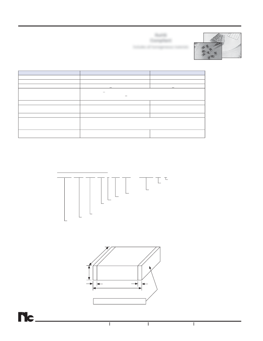
| high | 1.45 mm |
| JESD-609 code | e3 |
| length | 2 mm |
| Installation features | SURFACE MOUNT |
| multi-layer | Yes |
| negative tolerance | 10% |
| Number of terminals | 2 |
| Maximum operating temperature | 125 °C |
| Minimum operating temperature | -55 °C |
| Package shape | RECTANGULAR PACKAGE |
| Package form | SMT |
| method of packing | TR, PUNCHED |
| positive tolerance | 10% |
| Rated (DC) voltage (URdc) | 500 V |
| size code | 0805 |
| surface mount | YES |
| Temperature characteristic code | C0G |
| Temperature Coefficient | 30ppm/Cel ppm/°C |
| Terminal surface | Matte Tin (Sn) - with Nickel (Ni) barrier |
| Terminal shape | WRAPAROUND |
| width | 1.25 mm |
| Base Number Matches | 1 |
 京公网安备 11010802033920号


