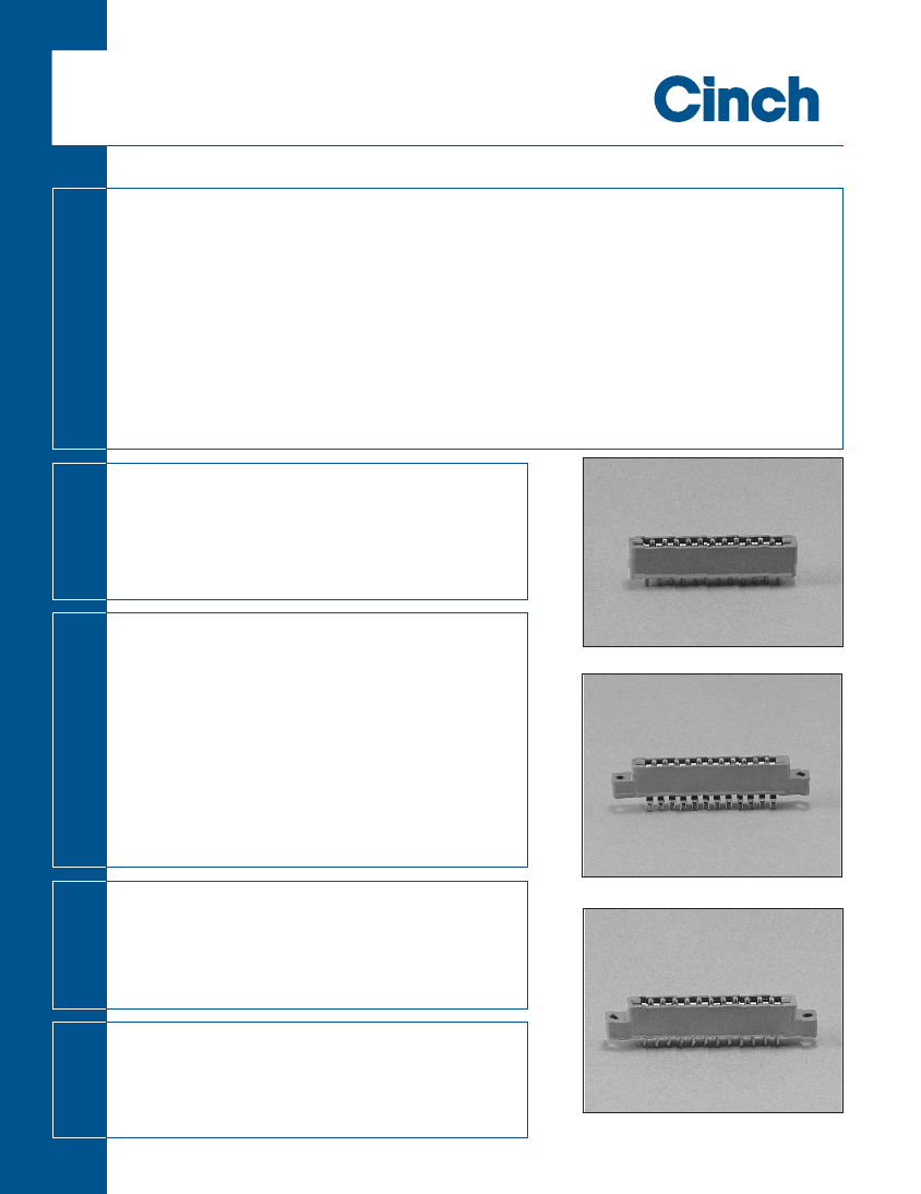
Card Edge Connector, 25 Contact(s), 1 Row(s), Female, Straight, 0.156 inch Pitch, Solder Terminal, Hole .125-.137, Green Insulator,
| Parameter Name | Attribute value |
| Maker | Cinch Connectivity Solutions |
| Reach Compliance Code | compliant |
| ECCN code | EAR99 |
| Other features | BIFURCATED BELLOWS CONTACTS, POLARIZATION AVAILABLE |
| body width | 0.34 inch |
| subject depth | 0.458 inch |
| body length | 4.754 inch |
| Connector type | CARD EDGE CONNECTOR |
| Contact to complete cooperation | AU |
| Contact completed and terminated | GOLD (5) |
| Contact point gender | FEMALE |
| Contact material | PHOSPHOR BRONZE |
| contact mode | RECTANGULAR |
| Contact resistance | 6 mΩ |
| Contact style | BELLOWED TYPE |
| DIN compliance | NO |
| Dielectric withstand voltage | 1800VAC V |
| Filter function | NO |
| IEC compliance | NO |
| maximum insertion force | 4.448 N |
| Insulation resistance | 5000000000 Ω |
| Insulator color | GREEN |
| insulator material | DIALLYL PHTHALATE |
| JESD-609 code | e4 |
| MIL compliance | NO |
| Manufacturer's serial number | 50 |
| Plug contact pitch | 0.156 inch |
| Mixed contacts | NO |
| Installation option 1 | HOLE .125-.137 |
| Installation method | STRAIGHT |
| Installation type | BOARD |
| Number of rows loaded | 1 |
| Maximum operating temperature | 105 °C |
| Minimum operating temperature | -65 °C |
| Options | GENERAL PURPOSE |
| Plating thickness | 30u inch |
| Rated current (signal) | 5 A |
| Guideline | UL |
| reliability | COMMERCIAL |
| Terminal length | 0.25 inch |
| Terminal pitch | 3.96 mm |
| Termination type | SOLDER |
| Total number of contacts | 25 |
| Evacuation force-minimum value | .278 N |
 京公网安备 11010802033920号


