Fixed Machined Contact Connector
D-DF S
ERIES
Standards:
• UL File:
E119881
• Connectors according to MIL C24308
S
PECIFICATIONS
:
M
ATERIALS
Shells
AND
P
LATINGS
Steel yellow chromated over zinc or tinned steel
with or without dimples on plug connector
Insulator
Glass-filled thermoplastic, UL 94V-0
Rear Insert
Brass, 118µ" up to 197µ" (3µm up to 5µm)
tinned over nickel 78µ" up to 118µ"
(2µm up to 3µm)
Boardlock
Tin-lead plating 157µ" up to 236µ"
(4µm up to 6µm) over nickel
78µ" up to 118µ" (2µm up to 3µm)
Screwlock
Brass, 236µ" up to 394µ"
(6µm up to 10µm) tinned over nickel 78µ"
up to 118µ" (2µm up to 3µm)
Contacts
D: brass
DF: pin = brass
Socket = copper alloy
Right Angle Version
Selective gold in mating area over 78µ"
up to 118µ"
(2µm up to 3µm) nickel; 118µ" up to 197µ"
(3µm up to 5µm) tin-lead on termination area
over 78µ" up to 118µ" (2µm up to 3µm) nickel
Straight Version
Full gold plating over 78µ" up to 118µ"
(2µm up to 3µm) nickel
The Amphenol SD series features
precision formed contacts, and 4
finger boardlocks.
This series gives you Amphenol’s
high standards of quality and
reliability to meet all of your
commercial requirements.
E
LECTRICAL
D
ATA
Current Rating
Voltage Rating
Withstanding Voltage
Insulation Resistance
Contact Resistance
7.5 A
300 V AC/rms 50Hz
1000V AC/rms 50Hz for one minute
5000MΩ
D: 8.5mΩ max.
DF: 5mΩ max.
• Industrial
• Telecom
• Any industry standard
I / O connections
C
LIMATIC
D
ATA
Operating Temperature
D: -67°F (-55°C) to +185°F (85°C),
peak at 257°F (125°C)
DF: -67°F (-55°C) to + 257°F (125°C)
M
ECHANICAL
D
ATA
No. of Contacts
9
15
25
37
50
(size E)
(size A)
(size B)
(size C)
(size D)
Mate (max.)
6.74 (3.05)
11.24 (5.09)
18.66 (8.44)
27.65 (12.51)
32.38 (14.65)
Unmate (min.)
0.79
1.01
1.8
2.47
3.56
(0.36)
(0.46)
(0.81)
(1.1)
(1.6)
I
NCHES
(
MM
)
20
T
ELEPHONE
: (416) 754-5656 F
AX
: (416) 754-8668
E-M
AIL
:
SALES
@
AMPHENOLCANADA
.
COM
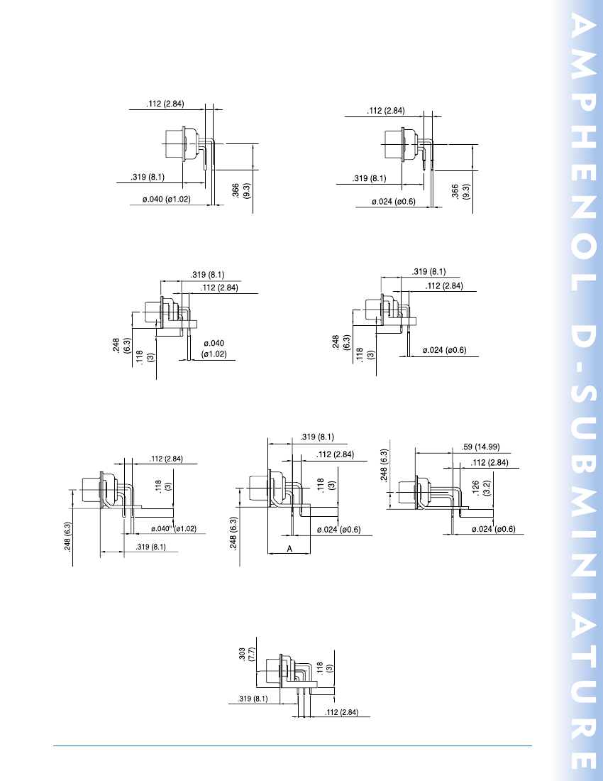
Screw-Machined Contacts
Fixed Machined Contact Connector
D-DF S
ERIES
For straight and R/A termination
#4-40 or M3
.134 (3.4)
Standard rivet Ø.120 (3.05)
no digit
#4-40 or M3
front screwlock
Float mounting
F
Threaded rear insert
H/G
#4-40 or M3
removable screwlock
.244 (6.2)
Fixed front female screwlock
VF / VFM
Removable female screwlock
VF2 / VFM2
R
ECOMMENDED
PCB L
AYOUT
For straight PCB:
X = .112 (2.84)
For right angle PCB:
MIL: X = .112 (2.84)
European: X = .100 (2.54), .112 (2.84) in option
size E
C ± .004 (0.1)
F ± .002 (0.05)
.984 (25)
.431 (10.96)
size A
1.311 (33.3)
.755 (19.18)
size B
1.85 (47)
1.304 (33.12)
size C
2.5
(63.5)
size D
2.406 (61.1)
1.74 (44.2)
1.956 (49.68)
I
NCHES
(
MM
)
24
T
ELEPHONE
: (416) 754-5656 F
AX
: (416) 754-8668 E-M
AIL
:
SALES
@
AMPHENOLCANADA
.
COM

 京公网安备 11010802033920号