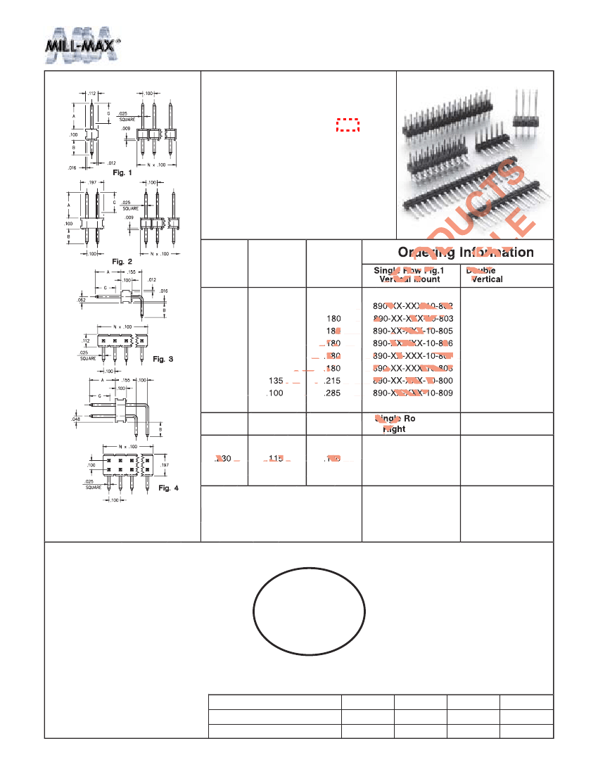
Board Connector, 12 Contact(s), 2 Row(s), Male, Straight, 0.1 inch Pitch, Solder Terminal, Black Insulator, Receptacle
| Parameter Name | Attribute value |
| Is it Rohs certified? | incompatible |
| Maker | Mill-Max |
| Reach Compliance Code | unknown |
| ECCN code | EAR99 |
| body width | 0.197 inch |
| subject depth | 0.1 inch |
| body length | 0.6 inch |
| Body/casing type | RECEPTACLE |
| Connector type | BOARD CONNECTOR |
| Contact to complete cooperation | TIN LEAD OVER NICKEL |
| Contact completed and terminated | Tin/Lead (Sn/Pb) - with Nickel (Ni) barrier |
| Contact point gender | MALE |
| Contact material | NOT SPECIFIED |
| contact mode | RECTANGULAR |
| Contact resistance | 6 mΩ |
| Contact style | SQ PIN-SKT |
| DIN compliance | NO |
| Dielectric withstand voltage | 1800VAC V |
| Filter function | NO |
| IEC compliance | NO |
| Insulation resistance | 10000000000 Ω |
| Insulator color | BLACK |
| insulator material | GLASS FILLED POLYAMIDE |
| JESD-609 code | e0 |
| MIL compliance | NO |
| Manufacturer's serial number | 892 |
| Plug contact pitch | 0.1 inch |
| Match contact row spacing | 0.1 inch |
| Plug information | MULTIPLE MATING PARTS AVAILABLE |
| Mixed contacts | NO |
| Installation method | STRAIGHT |
| Installation type | BOARD |
| Number of connectors | ONE |
| PCB row number | 2 |
| Number of rows loaded | 2 |
| Maximum operating temperature | 125 °C |
| Minimum operating temperature | -40 °C |
| Options | GENERAL PURPOSE |
| PCB contact pattern | RECTANGULAR |
| PCB contact row spacing | 2.54 mm |
| Plating thickness | 10u inch |
| Rated current (signal) | 3 A |
| Guideline | UL |
| reliability | COMMERCIAL |
| Terminal length | 0.125 inch |
| Terminal pitch | 2.54 mm |
| Termination type | SOLDER |
| Total number of contacts | 12 |
| UL Flammability Code | 94V-0 |
 京公网安备 11010802033920号


