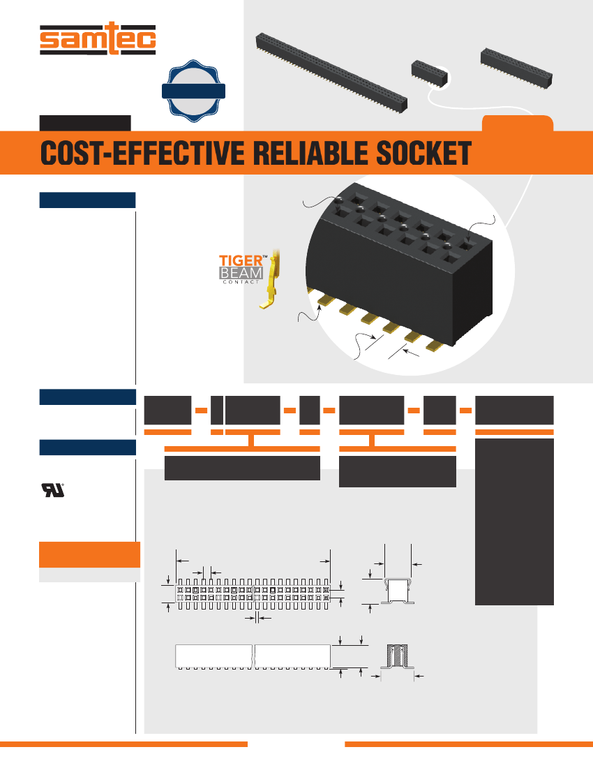
TWO PART BOARD CONNECTOR
| Parameter Name | Attribute value |
| Connector type | BOARD CONNECTOR |
| Contact materials | NOT SPECIFIED |
| Terminal spacing | 1.27 mm |
| Total number of contacts | 4 |
| Processing package description | ROHS COMPLIANT |
| each_compli | Yes |
| EU RoHS regulations | Yes |
| state | Active |
| width | 0.1310 inch |
| body_depth | 0.1720 inch |
| body_diamete | 0.1050 inch |
| Shell style | PLUG |
| Contact surface matching | NOT SPECIFIED |
| Contact coated terminals | NOT SPECIFIED |
| Connector male and female | FEMALE |
| contact_patte | RECTANGULAR |
| contact_resistance | 15 mohm |
| contact_style | SQ PIN-SKT |
| durability | 100 Cycles |
| insertion_force_max__n_ | .417 |
| insulator_col | BLACK |
| insulator_material | LIQUID CRYSTAL POLYMER (LCP) |
| Manufacturer Series | FLE |
| mating_contact_pitch__inch_ | 0.05 |
| mating_contact_row_spacing__inch_ | 0.05 |
| Installation method | STRAIGHT |
| Installation type | BOARD |
| umber_of_connectors | ONE |
| umber_of_pcb_rows | 2 |
| Number of load rows | 2 |
| Minimum operating temperature | -65 Cel |
| erating_temperature_max__cel_ | 125 |
| cb_contact_patte | RECTANGULAR |
| cb_contact_row_spacing__mm_ | 3.81 |
| lating_thickness__inch_ | 10u |
| ed_current__signal_ | 1.8 A |
| eference_standard | UL, CSA |
| eliability | COMMERCIAL |
| sub_category | Headers and Edge Type Connectors |
| erminal_length | 0.0 inch |
| Terminal type | SURFACE MOUNT |
| withdrawl_force_min__n_ | .417 |
| dditional_feature | TAPE&REEL PKG |
 京公网安备 11010802033920号


