*R
oH
VE S CO
AV R M
AI SIO PL
LA N IA
BL S NT
E
Features
■
Two channel quadrature output
■
Bushing or servo mount
■
Square wave signal
■
Small size
■
Resolution to 256 PPR
■
CMOS and TTL compatible
Non-RoHS models are currently
available, but not recommended
for new designs. See
Product
Obsolescence Memo
for details.
■
Long life
■
Ball bearing option for high operating
speed up to 3000 rpm
EN - Rotary Optical Encoder
Electrical Characteristics
Output ................................................................................... 2-bit quadrature code, Channel A leads Channel B by 90 º (electrical) with clockwise rotation
Resolution............................................................................................................................................................................... 25 to 256 cycles per revolution
Insulation Resistance (500 VDC) .................................................................................................................................................................. 1,000 megohms
Electrical Travel .....................................................................................................................................................................................................Continuous
Supply Voltage.........................................................................................................................................................................................5.0 VDC ±0.25 VDC
Supply Current.............................................................................................................................................................................................. 26 mA maximum
Output Voltage
Low Output .................................................................................................................................................................................................0.8 V maximum
High Output.....................................................................................................................................................................................................4 V minimum
Output Current
Low Output ................................................................................................................................................................................................ 25 mA minimum
Rise/Fall Time ..................................................................................................................................................................................................200 ns (typical)
Shaft RPM (Ball Bearing) ....................................................................................................................................................................... 3,000 rpm maximum
Power Consumption .................................................................................................................................................................................. 136 mW maximum
Pulse Width (Electrical Degrees, Each Channel) ............................................................................................................................................180 º ±45 º typ.
Pulse Width (Index Channel) ................................................................................................................................................................................. 360 º ±90 º
Phase (Electrical Degrees, Channel A to Channel B)........................................................................................................................................90 º ±45 º typ.
Environmental Characteristics
Operating Temperature Range .......................................................................................................................................-40 ºC to +75 ºC (-40 °F to +167 °F)
Storage Temperature Range ..........................................................................................................................................-40 °C to +85 °C (-40 °F to +185 °F)
Humidity................................................................................................................................................................. MIL-STD-202, Method 103B, Condition B
Vibration ............................................................................................................................................................................................................................ 5 G
Shock............................................................................................................................................................................................................................... 50 G
Rotational Life
A & C Bushings (300 rpm maximum)** ............................................................................................................................................10,000,000 revolutions
W, S & T Bushings (3,000 rpm maximum)** ..................................................................................................................................200,000,000 revolutions
IP Rating ..........................................................................................................................................................................................................................IP 40
Mechanical Characteristics
Mechanical Angle ........................................................................................................................................................................................ 360 ° Continuous
Torque (Starting and Running)
A & C Bushings (Spring Loaded for Optimum Feel) ..............................................................................................................1 N-cm (1.5 oz-in.) maximum
W, S & T Bushings (Ball Bearing Shaft Support) ..............................................................................................................0.07 N-cm (0.1 oz-in.) maximum
Mounting Torque ...................................................................................................................................................1.7 to 2.0 N-cm (15 to 18 lb.-in.) maximum
Shaft End Play .................................................................................................................................................................. 0.30 mm (0.012 ”) T.I.R. maximum
Shaft Radial Play .............................................................................................................................................................. 0.12 mm (0.005 ”) T.I.R. maximum
Weight .......................................................................................................................................................................................................... 11 gms. (0.4 oz.)
Terminals ......................................................................................................................................................................Axial or radial pc pins or ribbon cable
Soldering Condition
Manual Soldering ................................................................................................................... 96.5Sn/3.0Ag/0.5Cu solid wire or no-clean rosin cored wire
370 °C (700 °F) max. for 3 seconds
Wave Soldering ...........................................................................................................................................96.5Sn/3.0Ag/0.5Cu solder with no-clean flux
260 °C (500 °F) max. for 5 seconds
Wash processes .................................................................................................................................................................................... Not recommended
Marking .................................................................................................................................Manufacturer’s trademark, name, part number, and date code.
Hardware ................................................................. One lockwasher and one mounting nut supplied with each encoder, except on servo mount versions.
**For resolutions
≤
128 quadrature cycles per shaft revolution.
Quadrature Output Table
OUTPUT VOLTAGE
Channel A
Channel B
1 cycle
360
° ±
90
°
Clockwise rotation
STANDARD RESOLUTIONS AVAILABLE
(Full quadrature output cycles per shaft revolution)
25*
125
50*
128
64
200
100
256
For Non-Standard Resolutions—Consult Factory
* Channel B leads Channel A
*RoHS Directive 2002/95/EC Jan. 27, 2003 including annex and RoHS Recast 2011/65/EU June 8, 2011.
Specifications are subject to change without notice.
Customers should verify actual device performance in their specific applications.
GENERAL INFORMATION
The Bourns
®
EN model is a self-contained rotary optical encoder.
It produces a 2-bit quadrature signal which is suitable for digital
systems where both magnitude and direction of adjustment must
be provided. The EN encoder is ideal for use as a digital panel
control or as a position sensing device in applications where long
life, reliability, high resolution and precise linearity are critical.
The EN series encoder converts rotary input into electrical signals
which can be used by microprocessors without A/D conversion.
Bourns encoder output signals are square wave digital pulses which
do not require debounce circuitry. Both features make it possible
to significantly reduce the memory overhead, wiring and wiring inter-
connects required by other types of control devices.
EN optical encoders offer a useful rotational life of from 10 million to
200 million shaft revolutions, making them ideal for extended service
applications. The Bourns encoder is also compact and well suited for
situations where the available space is limited.
EN - Rotary Optical Encoder
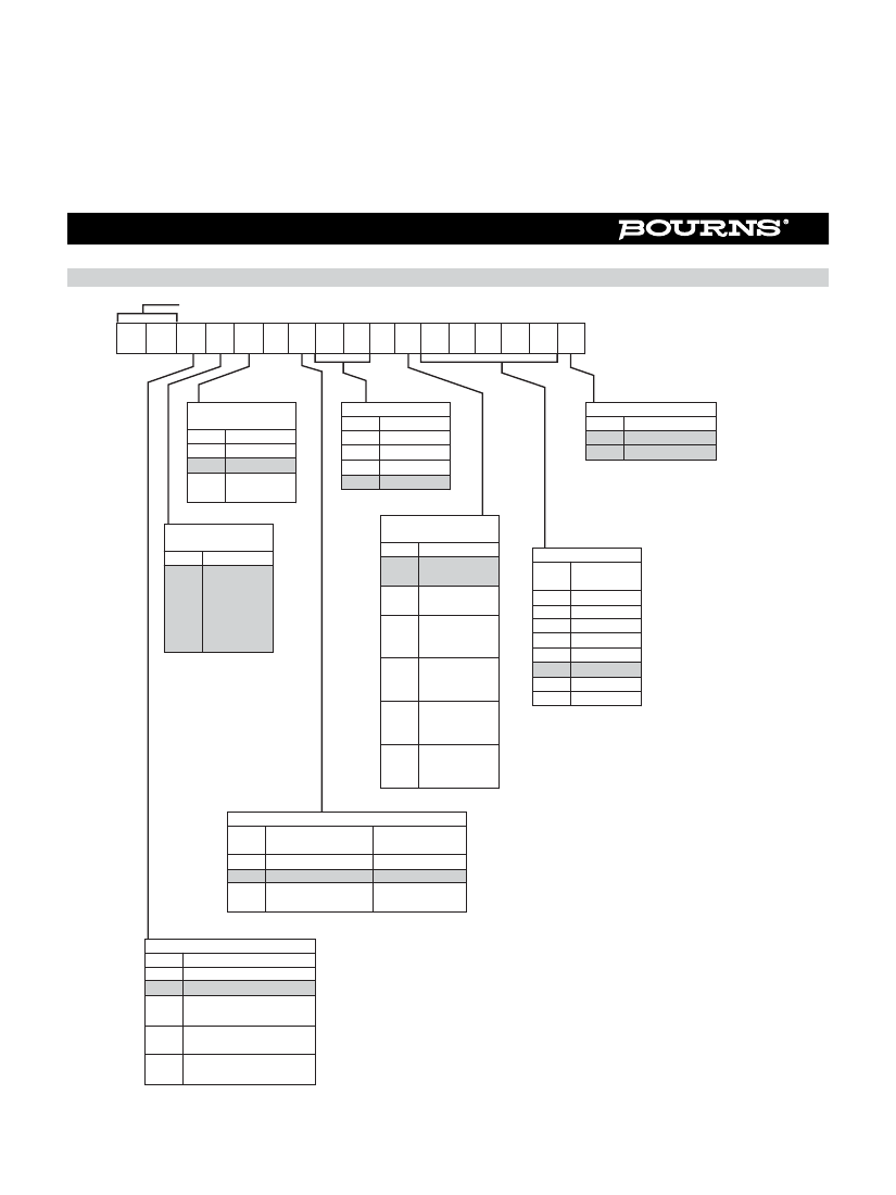
How To Order
BOURNS EN SERIES OPTICAL ENCODER
E N C 1 J - D 2 8 - L 0 0 1 2 8 L
ANTI-ROTATION
LUG POSITION
Code Description
None
D
9:00 Position
J
Rear Mount-
P
ing Bracket
SWITCHING
CONFIGURATION
Code Description
Channel A
Leads
Channel B
1
By 90
°
(Clockwise
Rotation)**
SHAFT LENGTH*
Code Description
1/2 " Long
16
5/8 " Long
20
3/4 " Long
24
7/8 " Long
28
RoHS IDENTIFIER
Code Description
L
Compliant
Blank Non-Compliant
Non-compliant versions are
available, but not recommended
for new designs.
TERMINAL***
CONFIGURATION
Code Description
L
Axial, Multi-
Purpose Pin
Radial, Multi-
R
Purpose Pin
Axial, Ribbon
M
& Connector
10 “
Radial, Ribbon
N
& Connector
10 ”
Axial, Ribbon
W
10 “ -
No Connector
Radial, Ribbon
Y
10 ” -
No Connector
RESOLUTION
Cycles Per
Code Revolution
25
00025
50
00050
64
00064
100
00100
125
00125
128
00128
200
00200
256
00256
SHAFT STYLE
Code
B
D
C
Description
1/4 " Dia., Plain End
1/8 " Dia., Plain End
1/4 " Dia., Single
Flatted
Use With
Bushings (Code)
A, S
C, T, W
A, S
BUSHING CONFIGURATION
Code Description
A
3/8 "D X 3/8 "L Threaded
C
1/4 "D X 1/4 "L Threaded
S
3/8 "D X 3/8 "L Threaded
(Ball Bearing)
1/4 "D X 3/8 "L Threaded
T
(Ball Bearing)
Servo Mount 7/8 "D
W
(Ball Bearing)
* Shaft length measured from mounting surface.
** 25 and 50 PPR is reversed (Channel B leads Channel A).
*** Standard ribbon cable is 10 " long. Consult factory for other lengths.
REV. 04/12
Specifications are subject to change without notice.
Customers should verify actual device performance in their specific applications.

 京公网安备 11010802033920号