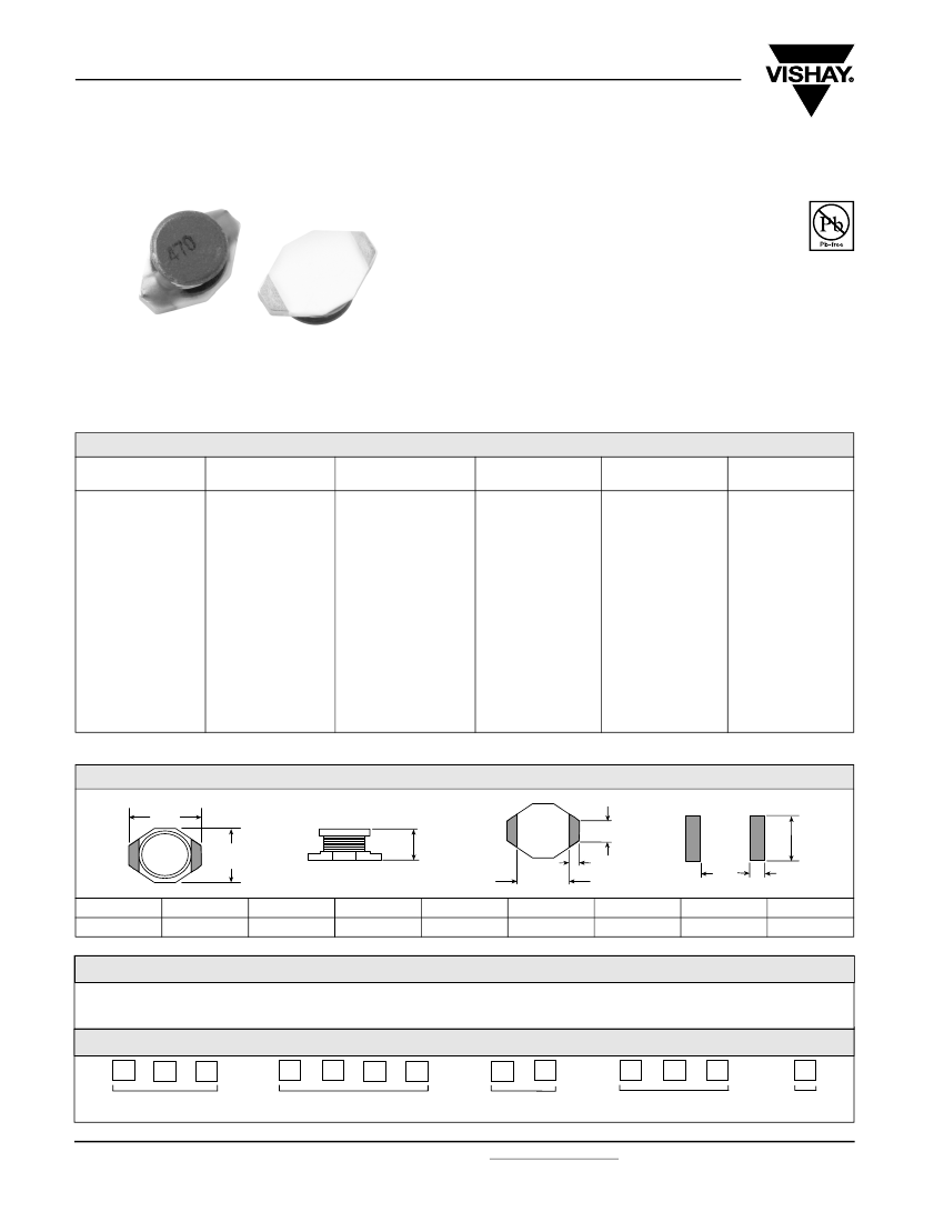
General Purpose Inductor, 100uH, 20%, 1 Element, Ferrite-Core, SMD
| Parameter Name | Attribute value |
| Is it Rohs certified? | incompatible |
| Maker | Vishay |
| Reach Compliance Code | compliant |
| ECCN code | EAR99 |
| core material | FERRITE |
| DC Resistance | 1.27 Ω |
| Nominal inductance(L) | 100 µH |
| Inductor Applications | HIGH CURRENT INDUCTOR |
| Inductor type | GENERAL PURPOSE INDUCTOR |
| Manufacturer's serial number | IDC-2512 |
| Number of functions | 1 |
| Number of terminals | 2 |
| Maximum operating temperature | 125 °C |
| Minimum operating temperature | -40 °C |
| Shape/Size Description | RECTANGULAR PACKAGE |
| shield | NO |
| surface mount | YES |
| Terminal location | DUAL ENDED |
| Terminal shape | WRAPAROUND |
| Test frequency | 0.1 MHz |
| Tolerance | 20% |
| IDC2512NB101M | IDC2512NB6R8M | IDC2512NB102M | IDC2512NB151M | IDC2512NB1R5M | IDC2512NB331M | IDC2512NB330M | IDC2512NB470M | IDC2512NB150M | |
|---|---|---|---|---|---|---|---|---|---|
| Description | General Purpose Inductor, 100uH, 20%, 1 Element, Ferrite-Core, SMD | General Purpose Inductor, 6.8uH, 20%, 1 Element, Ferrite-Core, SMD | General Purpose Inductor, 1000uH, 20%, 1 Element, Ferrite-Core, SMD | General Purpose Inductor, 150uH, 20%, 1 Element, Ferrite-Core, SMD | General Purpose Inductor, 1.5uH, 20%, 1 Element, Ferrite-Core, SMD | General Purpose Inductor, 330uH, 20%, 1 Element, Ferrite-Core, SMD | General Purpose Inductor, 33uH, 20%, 1 Element, Ferrite-Core, SMD | General Purpose Inductor, 47uH, 20%, 1 Element, Ferrite-Core, SMD | General Purpose Inductor, 15uH, 20%, 1 Element, Ferrite-Core, SMD |
| Is it Rohs certified? | incompatible | incompatible | incompatible | incompatible | incompatible | incompatible | incompatible | incompatible | incompatible |
| Reach Compliance Code | compliant | compliant | compliant | compliant | compliant | compliant | compliant | compliant | compliant |
| ECCN code | EAR99 | EAR99 | EAR99 | EAR99 | EAR99 | EAR99 | EAR99 | EAR99 | EAR99 |
| core material | FERRITE | FERRITE | FERRITE | FERRITE | FERRITE | FERRITE | FERRITE | FERRITE | FERRITE |
| DC Resistance | 1.27 Ω | 0.13 Ω | 13.8 Ω | 2 Ω | 0.05 Ω | 3.8 Ω | 0.51 Ω | 0.64 Ω | 0.23 Ω |
| Nominal inductance(L) | 100 µH | 6.8 µH | 1000 µH | 150 µH | 1.5 µH | 330 µH | 33 µH | 47 µH | 15 µH |
| Inductor Applications | HIGH CURRENT INDUCTOR | HIGH CURRENT INDUCTOR | HIGH CURRENT INDUCTOR | HIGH CURRENT INDUCTOR | HIGH CURRENT INDUCTOR | HIGH CURRENT INDUCTOR | HIGH CURRENT INDUCTOR | HIGH CURRENT INDUCTOR | HIGH CURRENT INDUCTOR |
| Inductor type | GENERAL PURPOSE INDUCTOR | GENERAL PURPOSE INDUCTOR | GENERAL PURPOSE INDUCTOR | GENERAL PURPOSE INDUCTOR | GENERAL PURPOSE INDUCTOR | GENERAL PURPOSE INDUCTOR | GENERAL PURPOSE INDUCTOR | GENERAL PURPOSE INDUCTOR | GENERAL PURPOSE INDUCTOR |
| Manufacturer's serial number | IDC-2512 | IDC-2512 | IDC-2512 | IDC-2512 | IDC-2512 | IDC-2512 | IDC-2512 | IDC-2512 | IDC-2512 |
| Number of functions | 1 | 1 | 1 | 1 | 1 | 1 | 1 | 1 | 1 |
| Number of terminals | 2 | 2 | 2 | 2 | 2 | 2 | 2 | 2 | 2 |
| Maximum operating temperature | 125 °C | 125 °C | 125 °C | 125 °C | 125 °C | 125 °C | 125 °C | 125 °C | 125 °C |
| Minimum operating temperature | -40 °C | -40 °C | -40 °C | -40 °C | -40 °C | -40 °C | -40 °C | -40 °C | -40 °C |
| Shape/Size Description | RECTANGULAR PACKAGE | RECTANGULAR PACKAGE | RECTANGULAR PACKAGE | RECTANGULAR PACKAGE | RECTANGULAR PACKAGE | RECTANGULAR PACKAGE | RECTANGULAR PACKAGE | RECTANGULAR PACKAGE | RECTANGULAR PACKAGE |
| shield | NO | NO | NO | NO | NO | NO | NO | NO | NO |
| surface mount | YES | YES | YES | YES | YES | YES | YES | YES | YES |
| Terminal location | DUAL ENDED | DUAL ENDED | DUAL ENDED | DUAL ENDED | DUAL ENDED | DUAL ENDED | DUAL ENDED | DUAL ENDED | DUAL ENDED |
| Terminal shape | WRAPAROUND | WRAPAROUND | WRAPAROUND | WRAPAROUND | WRAPAROUND | WRAPAROUND | WRAPAROUND | WRAPAROUND | WRAPAROUND |
| Test frequency | 0.1 MHz | 0.1 MHz | 0.1 MHz | 0.1 MHz | 0.1 MHz | 0.1 MHz | 0.1 MHz | 0.1 MHz | 0.1 MHz |
| Tolerance | 20% | 20% | 20% | 20% | 20% | 20% | 20% | 20% | 20% |
| Maker | Vishay | - | - | Vishay | Vishay | Vishay | Vishay | Vishay | Vishay |
 京公网安备 11010802033920号


