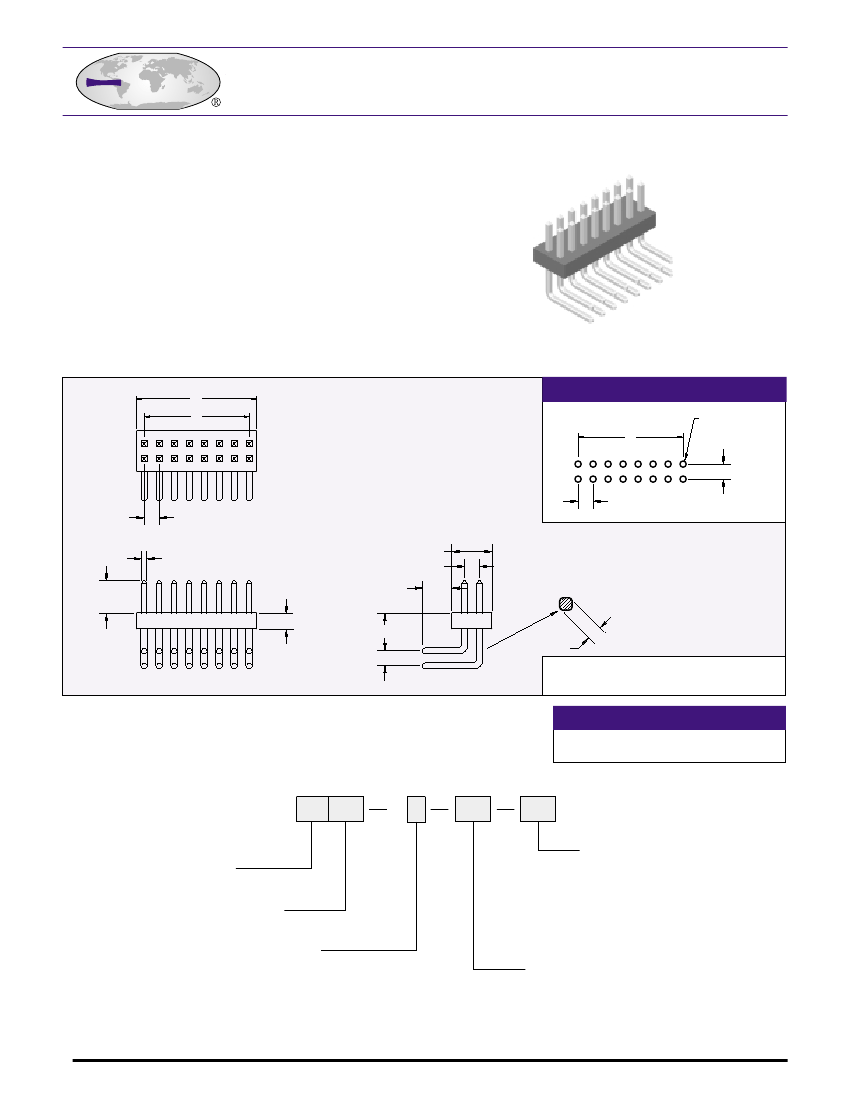
Board Connector, 42 Contact(s), 2 Row(s), Male, Right Angle, 0.05 inch Pitch, Solder Terminal, Receptacle
| Parameter Name | Attribute value |
| Maker | ECS |
| Reach Compliance Code | unknown |
| body width | 0.134 inch |
| subject depth | 0.182 inch |
| body length | 1.05 inch |
| Body/casing type | RECEPTACLE |
| Connector type | BOARD CONNECTOR |
| Contact to complete cooperation | SN ON NI |
| Contact completed and terminated | TIN OVER NICKEL |
| Contact point gender | MALE |
| Contact material | COPPER ALLOY |
| contact mode | RECTANGULAR |
| Contact style | SQ PIN-SKT |
| Dielectric withstand voltage | 500VAC V |
| Insulation resistance | 5000000000 Ω |
| Manufacturer's serial number | 9600 |
| Plug contact pitch | 0.05 inch |
| Match contact row spacing | 0.05 inch |
| Installation method | RIGHT ANGLE |
| Installation type | BOARD |
| Number of connectors | ONE |
| PCB row number | 2 |
| Number of rows loaded | 2 |
| Maximum operating temperature | 105 °C |
| Minimum operating temperature | -40 °C |
| PCB contact pattern | RECTANGULAR |
| PCB contact row spacing | 1.27 mm |
| Plating thickness | 100u inch |
| Rated current (signal) | 1 A |
| Guideline | UL |
| reliability | COMMERCIAL |
| Terminal length | 0.118 inch |
| Terminal pitch | 1.27 mm |
| Termination type | SOLDER |
| Total number of contacts | 42 |
 京公网安备 11010802033920号


