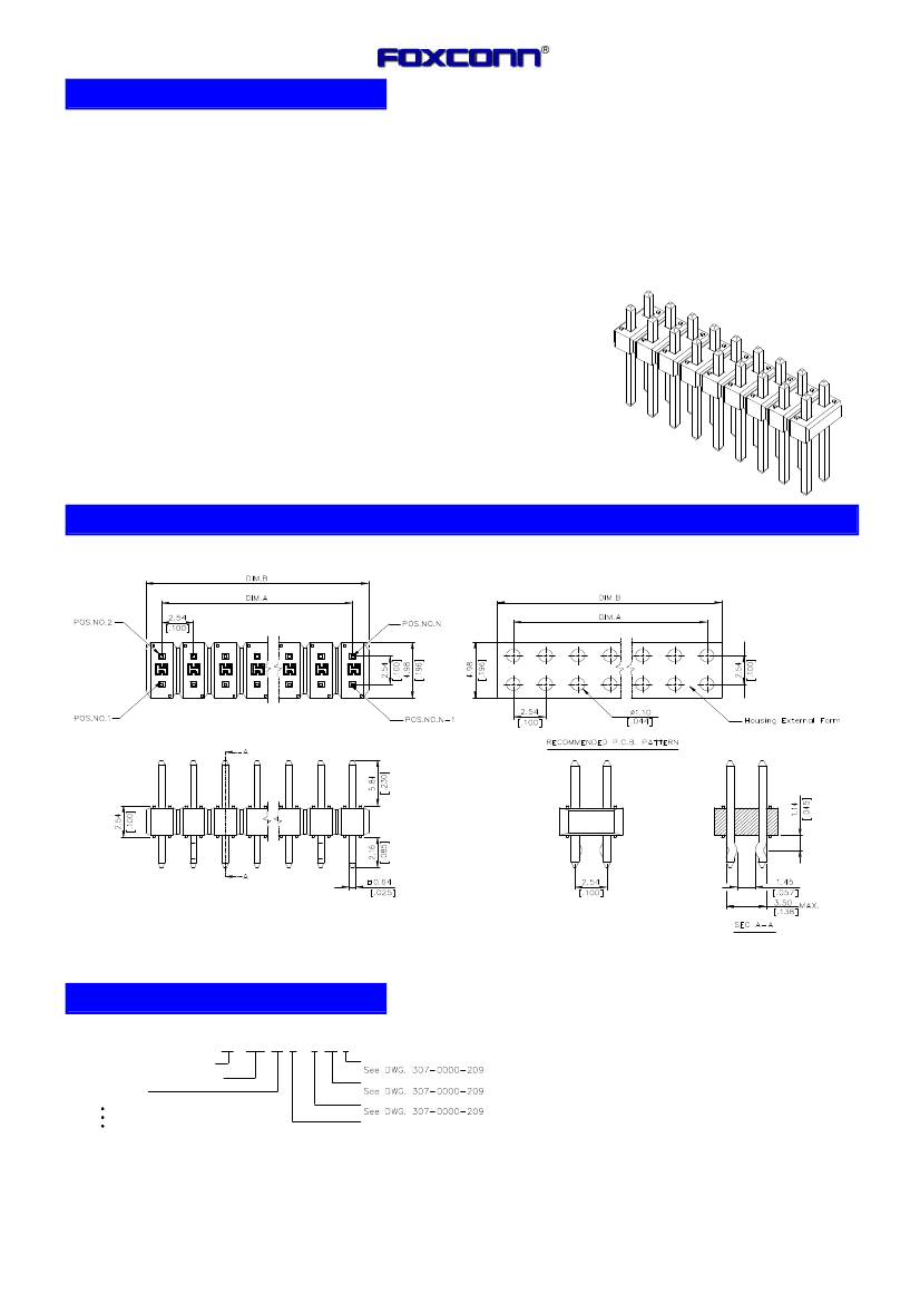
Board Connector, 26 Contact(s), 2 Row(s), Male, Straight, 0.1 inch Pitch, Solder Terminal, Red Insulator, Receptacle
| Parameter Name | Attribute value |
| Maker | FOXCONN |
| Reach Compliance Code | unknown |
| ECCN code | EAR99 |
| Other features | ROHS COMPLIANT |
| body width | 0.196 inch |
| subject depth | 0.1 inch |
| body length | 1.29 inch |
| Body/casing type | RECEPTACLE |
| Connector type | BOARD CONNECTOR |
| Contact to complete cooperation | AU |
| Contact point gender | MALE |
| Contact material | COPPER ALLOY |
| contact mode | RECTANGULAR |
| Contact style | SQ PIN-SKT |
| Dielectric withstand voltage | 500VAC V |
| Insulation resistance | 1000000000 Ω |
| Insulator color | RED |
| insulator material | GLASS FILLED NYLON |
| Manufacturer's serial number | HC19 |
| Plug contact pitch | 0.1 inch |
| Match contact row spacing | 0.1 inch |
| Installation method | STRAIGHT |
| Installation type | BOARD |
| Number of connectors | ONE |
| PCB row number | 2 |
| Number of rows loaded | 2 |
| Maximum operating temperature | 105 °C |
| Minimum operating temperature | -40 °C |
| PCB contact pattern | RECTANGULAR |
| PCB contact row spacing | 2.54 mm |
| Plating thickness | 15u inch |
| Rated current (signal) | 3 A |
| Guideline | UL |
| reliability | COMMERCIAL |
| Terminal length | 0.085 inch |
| Terminal pitch | 2.54 mm |
| Termination type | SOLDER |
| Total number of contacts | 26 |
Popular Components
EEWorld
subscription
account

EEWorld
service
account

Automotive
development
circle

Robot
development
community

 京公网安备 11010802033920号


