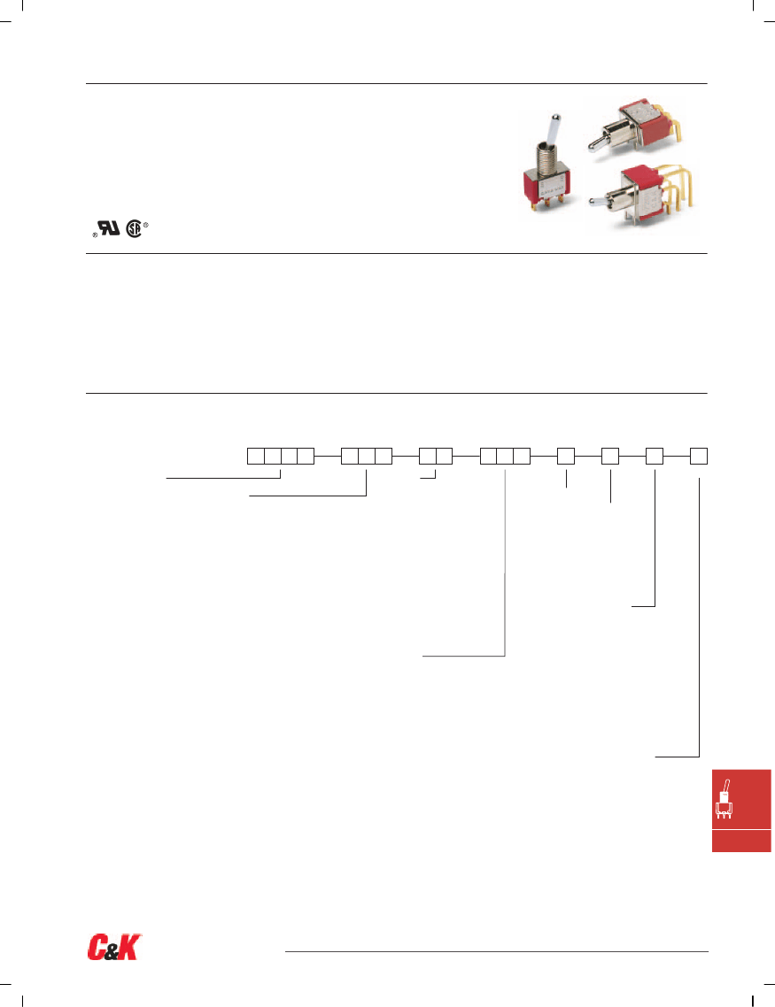
7000 Series
Miniature Toggle Switches
Features/Benefits
•
Multi-pole and multi-position
•
Wide variety of actuator and
termination options
Typical Applications
•
Telecommunications
•
Instrumentation
•
Medical equipment
•
Epoxy terminal-seal compatible
with bottom wash cleaning
•
RoHS complaint models available
Models Available
Specifications
CONTACT RATING: B contact material: 0.4 VA max. @ 20 V AC or
DC max. Q contact material: 5 AMPS @ 120 V AC or 28 V DC;
2 AMPS @ 250 V AC. See page F-15 for additional ratings.
ELECTRICAL LIFE: 7X01 and UX1 models: 100,000 make-and-break
cycles at full load. All other models: 40,000 cycles.
CONTACT RESISTANCE: Below 10 m
Ω
typ. initial @ 2-4 V DC,
100 mA, for both silver and gold plated contacts.
INSULATION RESISTANCE: 109
Ω
min.
DIELECTRIC STRENGTH: 1000 Vrms min. @ sea level.
OPERATING TEMPERATURE: –30ºC to 85ºC.
SOLDERABILITY: Per MIL-STD-202F method 208D, or EIA RS-186E
method 9 (1 hour steam aging).
For materials see page F-4.
NOTE:
Any models supplied with P, S R, Q, B or G contact material are RoHS compliant
and compatible.
NOTE:
Specifications listed above are for switches with standard options. For information
on specific and custom switches, consult Customer Service Center.
Build-A-Switch
To order, simply select desired option from each category and place in the appropriate box. Available options are shown and
described on pages F–4 thru F–16. For additional options not shown in catalog, consult our Customer Service Center.
Switch Function
7101
SP On-None-On
7103
SP On-Off-On
7105
SP Mom.-Off-Mom.
7107
SP On-Off-Mom.
7108
SP On-None-Mom.
7109
SP None-On-Mom.
7201
DP On-None-On
7203
DP On-Off-On
7205
DP Mom.-Off-Mom.
7207
DP On-Off-Mom.
7208
DP On-None-Mom.
7211
DP On-On-On
7213
DP On-On-Mom.
7215
DP Mom.-On-Mom.
7301
3P On-None-On
7303
3P On-Off-On
7305
3P Mom.-Off-Mom.
7308
3P On-None-Mom.
7401
4P On-None-On
7403
4P On-Off-On
7405
4P Mom.-Off-Mom.
7408
4P On-None-Mom.
7411
4P On-On-On
7413
4P On-On-Mom.
7415
4P Mom.-On-Mom.
Note:
UL/CSA models available,
see pages F-4 & F-5.
Actuator
M
.200" high
P3
Flatted, anti-rotation,
.450" high
S
.420" high
T
.687" high, 15/32 bushing
K2
Locking lever, .704" high
K9
Locking lever, .704" high
K12
Locking lever, .732" high
K19
Locking lever, .732" high
L
.840" high
L1
.640" high
L1P
Anti-rotation, .640" high
L2
.550" high
L2P
Anti-rotation, .550" high
L3
Plastic .940” inch
L40
Lever handle without cap
L41
.531" high lever handle with cap
L42
.838" high lever handle with cap
MP
Anti-rotation, .200" high
P1
Flatted, anti-rotation,
.840" high
P4
Flatted, anti-rotation,
.250" high
SP
Anti-rotation, .420" high
T1
.487" high, 15/32 bushing
T1P
Anti-rotation, .487" high,
15/32 bushing
T2P
Flatted, anti-rotation,
.610” high, 15/32 bushing,
TP
Anti-rotation, .687" high,
15/32 bushing
Bushing
D
.280 high, keyway
H
.296 high, flat
Y
.350 high, keyway
NONE
No bushing
choice required
CW
Splashproof
D8
.280" high, flat
D9
.280" high, keyway
H3
.315" high, keyway
H4
8mm high, keyway
Y1
.378" high, keyway
Y3
8.9mm high, keyway
Y4
.378" high, flat
Y9
.350" high, keyway
Contact Material
B
Gold
Seal
P
Gold, matte-tin
E
Epoxy
Q
Silver
I
Epoxy potted
S
Silver, matte-tin
base
G
Gold over silver
R
Gold over silver, matte-tin
Terminations
Right angle, PC thru-hole
A
AV2
Vert. right angle, PC thru-hole
C
PC Thru-hole
V3
.460 high, V-bracket
Z
Solder lug
A2
Right angle, PC thru-hole
A3
Right angle, PC thru-hole
A4
Right angle, PC thru-hole
AW1
Right angle, extended, PC thru-hole
AW4
Right angle, extended, PC thru-hole
V2
.555" high, V-bracket
V4
.630" high, V-bracket
V6
.460" high, V-bracket
V7
.630" high, V-bracket
V8
.953" high, V-bracket
W
V9
1.150" high, V-bracket
V21
.555" high, snap-in V-bracket
W1
V31
.460" high, snap-in V-bracket
W3
V41
.630" high, snap-in V-bracket
W4
W5
V71
.630" high, snap-in V-bracket
Z3
V81
.953" high, snap-in V-bracket
Actuator Color/Finish
NONE
Bright chrome
2
Black
3
Red
S
Satin chrome
KXX Actuator Color/Finish
NONE
Natural aluminum
2
Black anodized aluminum
3
Red anodized aluminum
7
Blue anodized aluminum
Bushing Finish
NONE
Nickel on all
bushings (except D8,
satin chrome)
2
Black
.750" long, wire wrap
.964" long, wire wrap
.425" long, wire wrap
1.062" long, wire wrap
1.305" long, wire wrap
Quick connect
F
Toggle
Dimensions are shown: Inches (mm)
Specifications and dimensions subject to change
F–3
www.ck-components.com
7000 Series
Miniature Toggle Switches
Materials
CASE: Glass filled nylon 6/6, flame retardant, heat stabilized, or
diallyl phthalate (DAP) (UL 94V-0).
ACTUATOR: Brass, chrome plated.
BUSHING: Brass or zinc, nickel plated.
HOUSING: Stainless steel.
SWITCH SUPPORT: Brass or steel, tin plated.
END CONTACTS: B contact material: Copper alloy, with gold plate
over nickel plate. Q contact material: Coin silver, silver plated.
See page F-15 for additional contact materials.
CENTER CONTACTS & ALL TERMINALS: B contact material: Copper
alloy, with gold plate over nickel plate. Q contact material: Copper
alloy, silver plated. See above for additional contact materials.
TERMINAL SEAL: Epoxy.
HARDWARE: Nut & Locking Ring: Brass, nickel plated.
Lockwasher: Steel, nickel plated.
NOTE:
Materials listed above are for switches with standard options. For information
on specific and custom switches, consult Customer Service Center.
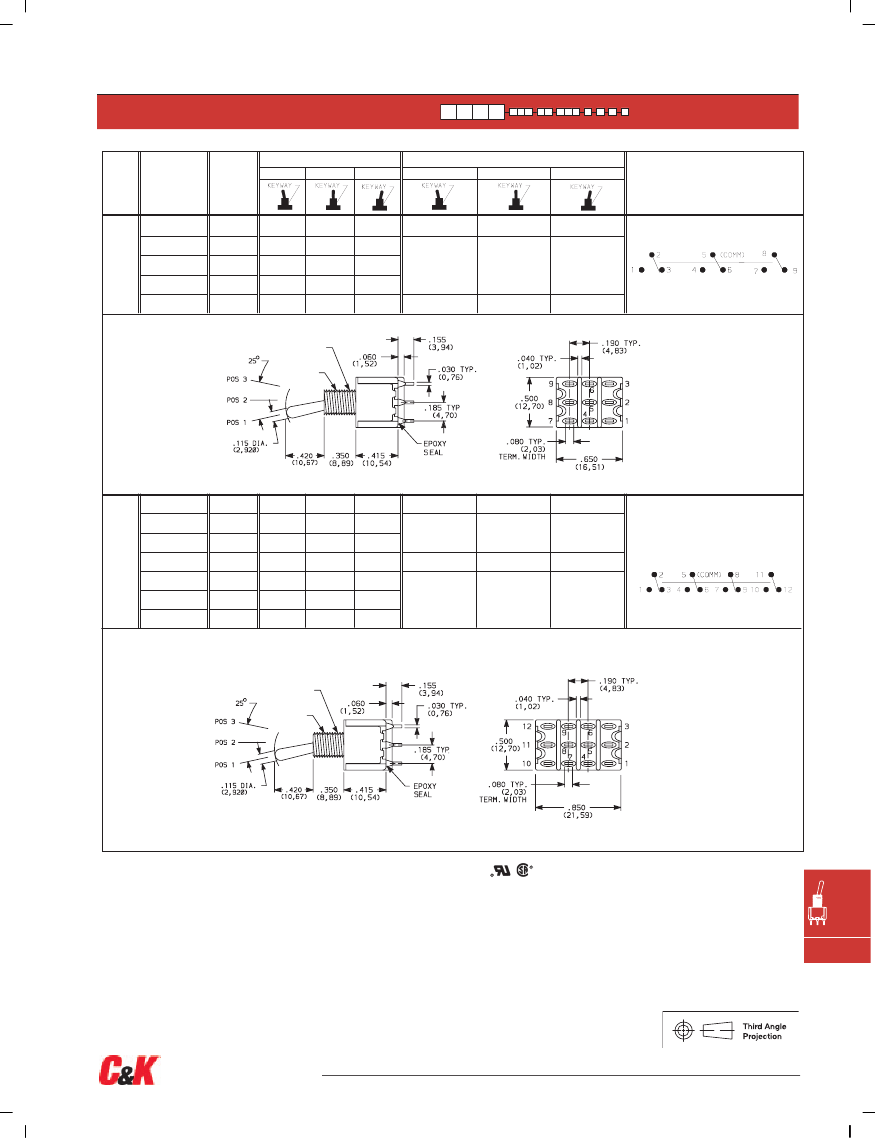
SWITCH FUNCTION
SWITCH FUNCTION
POS. 1
NO.
POLES
UL/CSA**
MODEL
NO.
POS. 2
POS. 3
CONNECTED TERMINALS
POS. 1
POS. 2
POS. 3
MODEL NO.
SCHEMATIC
ON
ON
MOM.
ON
ON
NONE
NONE
OFF
OFF
OFF
NONE
ON
ON
ON
MOM.
MOM.
MOM.
MOM.
2-3
N/A
N/A
2-3
2-1
2-1
SPDT
2-3
OPEN
2-1
2-3
N/A
2-1
7101
7103
7105
SP
U11
U13
U15
U17
U18
U19
7107
7108
7109
SPDT
1/4-40 UNS-2A
KEYWAY
Terminal Numbers
For Reference Only
Part number shown: 7101SYZBE
7201
7203
7205
7207
DP
U21
U23
U25
U27
U28
U211*
U213*
U215*
ON
ON
MOM.
ON
ON
ON
ON
MOM.
NONE
OFF
OFF
OFF
NONE
ON
ON
ON
ON
ON
MOM.
MOM.
MOM.
ON
MOM.
MOM.
2-3,5-6
N/A
2-1,5-4
2-3,5-6
OPEN
2-1,5-4
7208
7211
*
7213*
7215*
2-3,5-6
N/A
2-1,5-4
2-3,5-6
2-3,5-4
2-1,5-4
DPDT
DPDT
1/4-40 UNS-2A
KEYWAY
F
Terminal Numbers
For Reference Only
Part number shown: 7201SYZQE
MOM. = Momentary
* Wiring for 3-way switch, see Section N.
** U11–U415 model nos.
with all options when ordered with G, R, Q or S contact material.
Toggle
Dimensions are shown: Inches (mm)
Specifications and dimensions subject to change
F–4
www.ck-components.com
7000 Series
Miniature Toggle Switches
SWITCH FUNCTION
SWITCH FUNCTION
POS. 1
POS. 2
POS. 3
NO.
POLES
UL/CSA**
MODEL
NO.
CONNECTED TERMINALS
POS. 1
POS. 2
POS. 3
MODEL NO.
SCHEMATIC
ON
ON
MOM.
ON
ON
NONE
OFF
OFF
OFF
NONE
ON
ON
MOM.
MOM.
MOM.
2-3,5-6,8-9
N/A
2-1,5-4,8-7
3PDT
2-3,5-6,8-9
OPEN
2-1,5-4,8-7
2-3,5-6,8-9
N/A
2-1,5-4,8-7
7301
7303
3P
U31
U33
U35
U37
U38
7305
7307
7308
3PDT
1/4-40 UNS-2A
KEYWAY
Part number shown: 7301SYZQE
Terminal Numbers
For Reference Only
7401
7403
7405
7408
4P
U41
U43
U45
U48
U411*
U413*
U415*
ON
ON
MOM.
ON
ON
ON
MOM.
NONE
OFF
OFF
NONE
ON
ON
ON
ON
ON
MOM.
MOM.
ON
MOM.
MOM.
2-3,5-6,8-9,11-12
N/A
2-1,5-4,8-7,11-10
2-3,5-6,8-9,11-12
2-3,5-6,8-9,11-12
OPEN
N/A
2-1,5-4,8-7,11-10
2-1,5-4,8-7,11-10
7411*
7413*
7415*
4PDT
2-3,5-6,8-9,11-12
2-3,5-4,8-9,11-10
2-1,5-4,8-7,11-10
4PDT
1/4-40 UNS-2A
KEYWAY
Part number shown: 7401SYZQE
MOM. = Momentary
* Wiring for 3-way switch, see Section N.
** U11–U415 model nos.
Terminal Numbers
For Reference Only
with all options when ordered with G, Q, R or S contact material.
F
Toggle
Dimensions are shown: Inches (mm)
Specifications and dimensions subject to change
F–5
www.ck-components.com
7000 Series
Miniature Toggle Switches
ACTUATOR FINISH
ACTUATOR
ACTUATOR
S
SP
.420" HIGH
1
ANTIROTATION, .420" HIGH
2,3
M
MP
.200" HIGH
1
ANTIROTATION, .200" HIGH
2,3
L, L1, L2
L1P, L2P
.840", .640", .550" HIGH
1
ANTIROTATION,
.840", .640", .550" HIGH
2,3
*
*
*
DIM. ‘A’
OPTION
CODE
L
L1, L1P
L2, L2P
DIM ‘A’
.840 (21,34)
.640 (16,26)
.550 (13,97)
S actuator standard when ordered with
C, W-W5, Z & Z3 terminations.
Caps are available separately, see page F-16.
M actuator standard when ordered with
all terminations except C, W-W5, Z & Z3.
Caps are available separately, see page F-16.
Caps are available separately, see page F-16.
*P1
FLATTED WITH ANTIROTATION, .840" HIGH
2,3
*P3
FLATTED WITH ANTIROTATION,
.450" HIGH
2,3
*P4
FLATTED WITH ANTIROTATION, .250" HIGH
2,3
*
*
*
*Dress nut part number 709901201 supplied standard with threaded bushing. (Part number 709903201 with metric threaded bushings.)
T
TP
.687 (17,45) HIGH
1,2
ANTIROTATION, .687 (17,45) HIGH,
15/32 BUSHING
1,2,3
T1
T1P
.487 (12,37) HIGH
1,2
ANTIROTATION, .487 (12,37) HIGH,
15/32 BUSHING
1,2,3
T2P
FLATTED, ANTIROTATION, .610" HIGH,
15/32 BUSHING
1,2,3
.687
(17,45)
15/32-32 UNS-2A
.487
(12,37)
15/32-32 UNS-2A
15/32-32 UNS-2A
.448
(11,38)
Bushing option code not required unless CW splashproof bushing ordered. TP & T1P
actuators not available with CW splashproof bushing. All TXX actuators not available on
single pole models with A-A4, AW1-AW4 terminations.
Bushing option code not required. T2P actuator not available
with CW splashproof bushing or single pole models with
A-A4, AW1-AW4 terminations.
1
L, L1, L2, M, S & TXX actuators not available
with Y1 bushing.
F
OPTION
CODE
ACTUATOR FINISH
BRIGHT CHROME-With Nickel Plated Bushing
BLACK
SATIN CHROME
2
L1P, L2P, MP, P1, P3, P4, SP & TXX actuators not
NOTE:
Black hardware is supplied when either
black actuators or bushings are specified. For
additional hardware, see Section N.
available with D8 & H4 bushing.
3
Antirotation: Provides anti-‘push-in’ feature on
actuator.
NONE
2
S
Toggle
* Add .070 (1,78) for D, D8 & D9 bushings,
subtract .020 (0,51) for H3 bushing.
Dimensions are shown: Inches (mm)
Specifications and dimensions subject to change
F–6
www.ck-components.com
7000 Series
Miniature Toggle Switches
ACTUATOR FINISH/COLOR
ACTUATOR
ACTUATOR
K2
K9
LOCKING LEVER, .704" HIGH
(threaded)
LOCKING LEVER, .704" HIGH
(unthreaded)
K12
K19
LOCKING LEVER, .732" HIGH
(threaded)
LOCKING LEVER, .732" HIGH
(unthreaded)
OPTION
CODE
ACTUATOR CAP FINISH
NATURAL ALUMINUM–With Nickle Plated Bushing
BLACK ANODIZED ALUMINUM
RED ANODIZED ALUMINUM
BLUE ANODIZED ALUMINUM
NONE
2
*
*
3
7
* All KXX models including KXXCW have a keyway
Replaces K, K8
Replaces K1, K18
Locking Positions
NOTE:
To prevent accidental actuation, toggle must be lifted
before being actuated. When released, toggle will lock in place.
Overtightening mounting nut may cause actuator to bind.
Locking levers supplied with bushing shown.
Bushing option code not required unless CW splashproof
bushing ordered.
–01 Models
2 Position lock
–03 & –11 Models
3 Position lock
–05, –09 & –15 Models
1 Position lock
–07 & –13 Models
2 Position lock
–08 Models
1 Position lock
L40
LEVER HANDLE WITHOUT CAP
L41
PLASTIC LEVER HANDLE WITH
ANTIROTATION AND CAP, P/N 4810
L42
PLASTIC LEVER HANDLE WITH
ANTIROTATION AND CAP, P/N 4811
No color choice required.
Finish: Matte (L41 & L42).
L3
PLASTIC .940” HIGH
Gloss Plastic
*
Chrome Finish
OPTION
CODE
PLASTIC ACTUATOR
COLORS
No Actuator Color (L40 option)
BLACK
RED
NONE
2
3
F
* Add .070 (1,78) for D, D8 & D9 bushings,
subtract .020 (0,51) for H3 bushing.
NOTE:
Lever handle for L41 & L42 actuators supplied, but not installed. For interchangeability,
order L40 actuator option and lever handles separately, see page F-16. L4X actuators not
available with H4, Y1, Y4 bushings. Antirotation: Provides anti-‘push-in’ feature on actuator.
Toggle
Dimensions are shown: Inches (mm)
Specifications and dimensions subject to change
F–7
www.ck-components.com

 京公网安备 11010802033920号