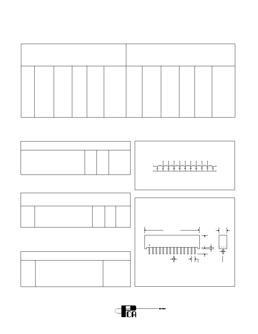
14 Pin Single-in-Line Package Passive Delay Lines
| Parameter Name | Attribute value |
| Is it lead-free? | Contains lead |
| Is it Rohs certified? | incompatible |
| Maker | PCA Electronics Inc. |
| Parts packaging code | SIP |
| package instruction | SIP-14 |
| Contacts | 14 |
| Reach Compliance Code | compliant |
| Other features | MAX RISE TIME CAPTURED |
| Input frequency maximum value (fmax) | 20 MHz |
| JESD-30 code | R-XSIP-T14 |
| JESD-609 code | e0 |
| Logic integrated circuit type | PASSIVE DELAY LINE |
| Humidity sensitivity level | 3 |
| Number of functions | 1 |
| Number of taps/steps | 10 |
| Number of terminals | 14 |
| Maximum operating temperature | 70 °C |
| Minimum operating temperature | |
| Output impedance nominal value (Z0) | 50 Ω |
| Output polarity | TRUE |
| Package body material | UNSPECIFIED |
| encapsulated code | SIP |
| Package shape | RECTANGULAR |
| Package form | IN-LINE |
| Peak Reflow Temperature (Celsius) | NOT SPECIFIED |
| programmable delay line | NO |
| Certification status | Not Qualified |
| Maximum seat height | 9.525 mm |
| surface mount | NO |
| technology | HYBRID |
| Temperature level | COMMERCIAL |
| Terminal surface | Tin/Lead (Sn/Pb) |
| Terminal form | THROUGH-HOLE |
| Terminal pitch | 2.54 mm |
| Terminal location | SINGLE |
| Maximum time at peak reflow temperature | NOT SPECIFIED |
| Total delay nominal (td) | 10 ns |
| Base Number Matches | 1 |
 京公网安备 11010802033920号


