
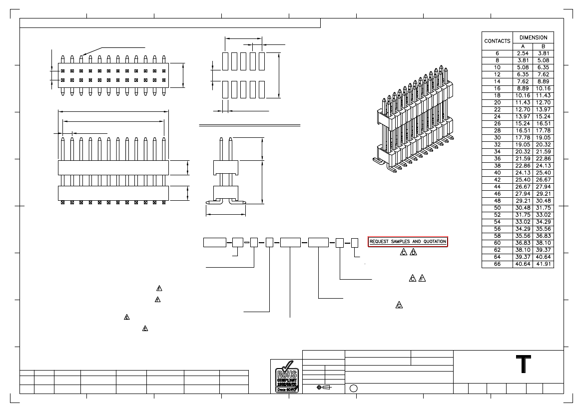
Board Connector, 34 Contact(s), 2 Row(s), Male, Straight, 0.05 inch Pitch, Surface Mount Terminal, Locking, Black Insulator,
| Parameter Name | Attribute value |
| Is it Rohs certified? | conform to |
| Objectid | 313796459 |
| Reach Compliance Code | compliant |
| ECCN code | EAR99 |
| Other features | TAPE AND REEL WITH CAP |
| body width | 0.134 inch |
| subject depth | 0.118 inch |
| body length | 0.85 inch |
| Connector type | BOARD CONNECTOR |
| Contact to complete cooperation | AU ON NI |
| Contact completed and terminated | GOLD OVER NICKEL |
| Contact point gender | MALE |
| Contact material | COPPER ALLOY |
| contact mode | RECTANGULAR |
| Contact resistance | 20 mΩ |
| Contact style | SQ PIN-SKT |
| Dielectric withstand voltage | 300VAC V |
| Durability | 100 Cycles |
| maximum insertion force | 2.0016 N |
| Insulation resistance | 1000000000 Ω |
| Insulator color | BLACK |
| insulator material | LIQUID CRYSTAL POLYMER (LCP) |
| Manufacturer's serial number | BD040 |
| Plug contact pitch | 0.05 inch |
| Match contact row spacing | 0.05 inch |
| Installation option 1 | LOCKING |
| Installation method | STRAIGHT |
| Installation type | BOARD |
| Number of connectors | ONE |
| PCB row number | 2 |
| Number of rows loaded | 2 |
| Maximum operating temperature | 105 °C |
| Minimum operating temperature | -40 °C |
| PCB contact pattern | RECTANGULAR |
| PCB contact row spacing | 6.5024 mm |
| Plating thickness | FLASH inch |
| polarization key | POLARIZED HOUSING |
| Rated current (signal) | 1 A |
| Guideline | UL |
| reliability | COMMERCIAL |
| Terminal pitch | 1.27 mm |
| Termination type | SURFACE MOUNT |
| Total number of contacts | 34 |
| Evacuation force-minimum value | .15012 N |
 京公网安备 11010802033920号


