
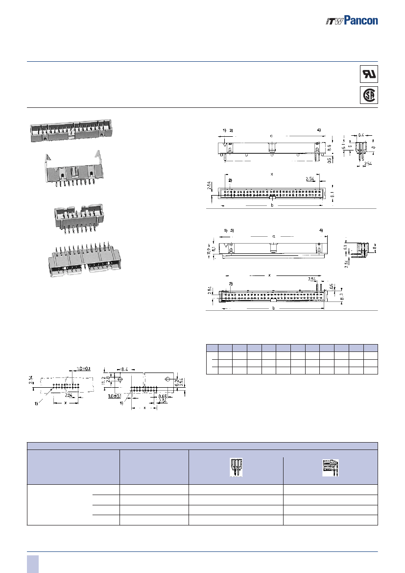
Board Euro Connector, 26 Contact(s), 2 Row(s), Male, Right Angle, 0.1 inch Pitch, Solder Terminal, Locking, Gray Insulator,
| Parameter Name | Attribute value |
| Is it lead-free? | Lead free |
| Is it Rohs certified? | conform to |
| Maker | PANCON CONNECTORS |
| Reach Compliance Code | compliant |
| Is Samacsys | N |
| Other features | LAT-CON, LOW PROFILE |
| body width | 0.347 inch |
| subject depth | 0.525 inch |
| body length | 1.6 inch |
| Connector type | BOARD EURO CONNECTOR |
| Contact to complete cooperation | NOT SPECIFIED |
| Contact point gender | MALE |
| Contact material | NOT SPECIFIED |
| contact mode | RECTANGULAR |
| Contact resistance | 20 mΩ |
| Contact style | SQ PIN-SKT |
| DIN compliance | YES |
| Dielectric withstand voltage | 1400VAC V |
| Durability | 250 Cycles |
| Filter function | NO |
| IEC compliance | NO |
| Insulation resistance | 1000000000 Ω |
| Insulator color | GRAY |
| MIL compliance | NO |
| Plug contact pitch | 0.1 inch |
| Match contact row spacing | 0.1 inch |
| Mixed contacts | NO |
| Installation option 1 | LOCKING |
| Installation method | RIGHT ANGLE |
| Installation type | BOARD |
| Number of connectors | ONE |
| PCB row number | 2 |
| Number of rows loaded | 2 |
| Maximum operating temperature | 105 °C |
| Minimum operating temperature | -40 °C |
| Options | GENERAL PURPOSE |
| PCB contact pattern | RECTANGULAR |
| PCB contact row spacing | 2.54 mm |
| polarization key | POLARIZED HOUSING |
| Rated current (signal) | 3 A |
| Guideline | UL |
| reliability | COMMERCIAL |
| Terminal length | 0.114 inch |
| Terminal pitch | 2.54 mm |
| Termination type | SOLDER |
| Total number of contacts | 26 |
| Base Number Matches | 1 |
 京公网安备 11010802033920号


