Cache SRAM, 256KX36, 3.5ns, CMOS, PBGA119, 14 X 22 MM, 2.40 MM HEIGHT, PLASTIC, BGA-119
| Parameter Name | Attribute value |
| Is it lead-free? | Contains lead |
| Is it Rohs certified? | incompatible |
| Parts packaging code | BGA |
| package instruction | BGA, BGA119,7X17,50 |
| Contacts | 119 |
| Reach Compliance Code | compliant |
| ECCN code | 3A991.B.2.A |
| Is Samacsys | N |
| Maximum access time | 3.5 ns |
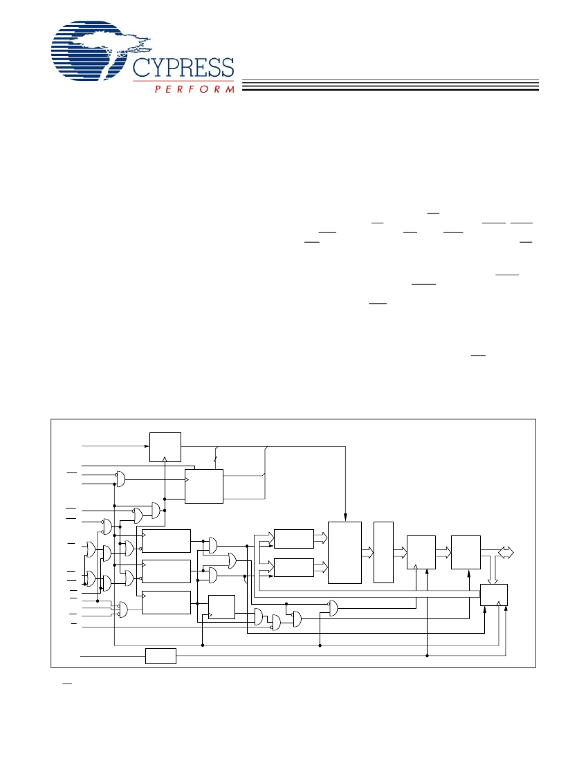
| Other features | PIPELINED ARCHITECTURE |
| Maximum clock frequency (fCLK) | 166 MHz |
| I/O type | COMMON |
| JESD-30 code | R-PBGA-B119 |
| JESD-609 code | e0 |
| length | 22 mm |
| memory density | 9437184 bit |
| Memory IC Type | CACHE SRAM |
| memory width | 36 |
| Humidity sensitivity level | 3 |
| Number of functions | 1 |
| Number of terminals | 119 |
| word count | 262144 words |
| character code | 256000 |
| Operating mode | SYNCHRONOUS |
| Maximum operating temperature | 85 °C |
| Minimum operating temperature | -40 °C |
| organize | 256KX36 |
| Output characteristics | 3-STATE |
| Package body material | PLASTIC/EPOXY |
| encapsulated code | BGA |
| Encapsulate equivalent code | BGA119,7X17,50 |
| Package shape | RECTANGULAR |
| Package form | GRID ARRAY |
| Parallel/Serial | PARALLEL |
| Peak Reflow Temperature (Celsius) | 220 |
| power supply | 2.5/3.3,3.3 V |
| Certification status | Not Qualified |
| Maximum seat height | 2.4 mm |
| Maximum standby current | 0.04 A |
| Minimum standby current | 3.14 V |
| Maximum slew rate | 0.18 mA |
| Maximum supply voltage (Vsup) | 3.6 V |
| Minimum supply voltage (Vsup) | 3.135 V |
| Nominal supply voltage (Vsup) | 3.3 V |
| surface mount | YES |
| technology | CMOS |
| Temperature level | INDUSTRIAL |
| Terminal surface | Tin/Lead (Sn/Pb) |
| Terminal form | BALL |
| Terminal pitch | 1.27 mm |
| Terminal location | BOTTOM |
| Maximum time at peak reflow temperature | 20 |
| width | 14 mm |
| Base Number Matches | 1 |
 京公网安备 11010802033920号


