

DUOPLUG MKI STD,6 POS, KEYED 4
| Parameter Name | Attribute value |
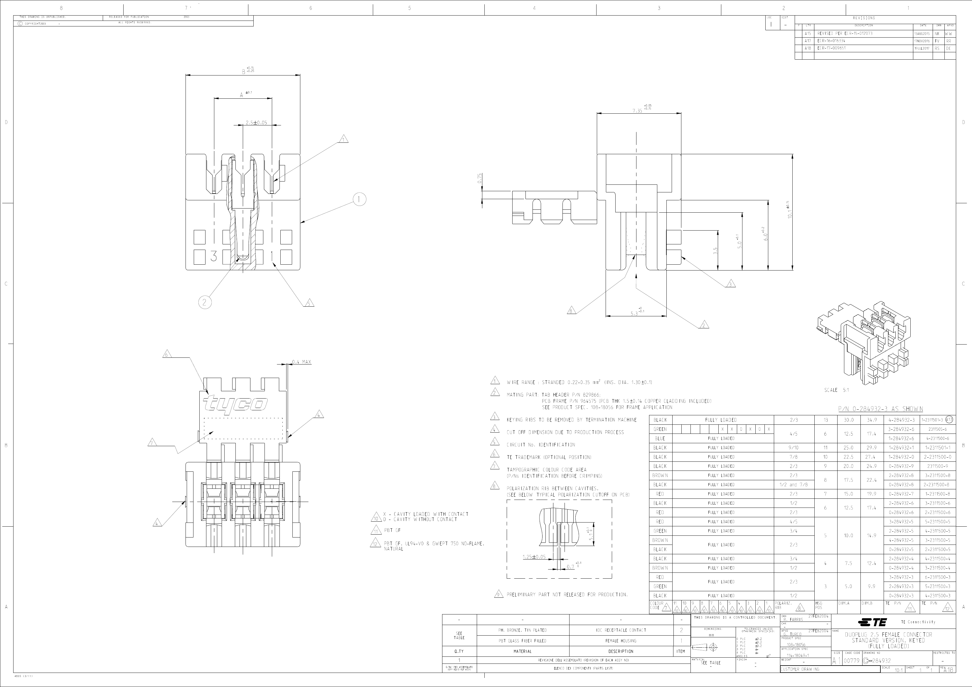
| Connector System | wire to board |
| Connector type | female end |
| Connectors and terminals terminate to | A printed circuit board |
| Connector type | card edge |
| Connector type | Connector components |
| shape | standard |
| Cable type | Stranded wire |
| Number of power supply locations | 6 |
| Number of Positions | 6 |
| Rows | 1 |
| Connector terminal load status | selective loading |
| PCB mounting direction | right angle |
| Pre-installed | yes |
| Card entry method | side |
| Support | Without |
| pre-assembled | yes |
| hot swap | no |
| Operating Voltage | 63 V |
| Keying between cavity number | 41734 |
| color | green |
| Cable exit angle | 90° |
| Terminal base material | Phosphor bronze |
| Contact Current Rating (Max) (A) | 2 |
| Terminal contact plating material | tin |
| Terminal termination area plating material | tin |
| Terminal termination area plating thickness (µm) | 4 – 10 |
| Terminal type | socket |
| Cable termination method | Piercing crimping (IDC) |
| PCB installation and fixation | Without |
| Panel mount features | Without |
| PCB mounting alignment | Without |
| Lock clip position | none |
| Connector mounting type | board mounting |
| Terminal positioning force | Without |
| joint fixation | Without |
| Joint alignment type | keying |
| joint alignment | with |
| Centerline (Pitch) | 2.5 mm [ .098 in ] |
| Shell color | green |
| Shell material | PBT GF |
| end cap | Without |
| Shell type | closed end |
| Accepts Wire Insulation Diameter Range | 1.3 mm [ .05 in ] |
| PCB thickness (recommended) | 1.5 mm [ .059 in ] |
| Cable size | 24 – 22 AWG [ .22 – .35 mm² ] |
| high | 7.35 mm [ .29 in ] |
| Acceptable wire insulation diameter range | 1.3 mm [ .051 in ] |
| card slot depth | 5 mm [ .2 in ] |
| Working group temperature range | -40 – 110 °C [ -40 – 230 °F ] |
| Circuit Application | Signal |
| Applicable to | PCB frame, male header |
| Package quantity | 280 |
| Encapsulation method | tray |
| 3-284932-6 | 284932-4 | 284932-5 | 284932-3 | 2-284932-4 | 284932-9 | 284932-6 | |
|---|---|---|---|---|---|---|---|
| Description | DUOPLUG MKI STD,6 POS, KEYED 4 | DUOPLUG MKI STD,KEYED 1/2,4 POS, BROWN | DUOPLUG STD FEMALE CONN.KEYED 2/3 5 POS | DUOPLUG Standard, female conn. | DUOPLUG MKI STD,KEYED 3/4,4 POS,BLACK | DUOPLUG MKI STD,KEYED 2/3,9 POS,BLACK | DUOPLUG MKI, KEYED 2/3, 6 POS, RED |
| Connector System | wire to board | wire to board | wire to board | wire to board | wire to board | wire to board | wire to board |
| Connectors and terminals terminate to | A printed circuit board | A printed circuit board | A printed circuit board | A printed circuit board | A printed circuit board | A printed circuit board | A printed circuit board |
| shape | standard | standard | standard | standard | standard | standard | standard |
| Cable type | Stranded wire | Stranded wire | Stranded wire | Stranded wire | Stranded wire | Stranded wire | Stranded wire |
| Number of Positions | 6 | 4 | 5 | 3 | 4 | 9 | 6 |
| Rows | 1 | 1 | 1 | 1 | 1 | 1 | 1 |
| Connector terminal load status | selective loading | Fully loaded | Fully loaded | Fully loaded | Fully loaded | Fully loaded | Fully loaded |
| PCB mounting direction | right angle | right angle | right angle | right angle | right angle | right angle | right angle |
| Pre-installed | yes | yes | yes | yes | yes | yes | yes |
| Card entry method | side | side | side | side | side | side | side |
| Support | Without | Without | Without | Without | Without | Without | Without |
| pre-assembled | yes | yes | yes | yes | yes | yes | yes |
| hot swap | no | no | no | no | no | no | no |
| Operating Voltage | 63 V | 63 V | 63 V | 63 V | 63 V | 63 V | 63 V |
| color | green | brown | black | black | black | black | red |
| Cable exit angle | 90° | 90° | 90° | 90° | 90° | 90° | 90° |
| Terminal base material | Phosphor bronze | Phosphor bronze | Phosphor bronze | Phosphor bronze | Phosphor bronze | Phosphor bronze | Phosphor bronze |
| Contact Current Rating (Max) (A) | 2 | 2 | 2 | 2 | 2 | 2 | 2 |
| Terminal contact plating material | tin | tin | tin | tin | tin | tin | tin |
| Terminal termination area plating material | tin | tin | tin | tin | tin | tin | tin |
| Terminal termination area plating thickness (µm) | 4 – 10 | 4 – 10 | 4 – 10 | 4 – 10 | 4 – 10 | 4 – 10 | 4 – 10 |
| Terminal type | socket | socket | socket | socket | socket | socket | socket |
| Cable termination method | Piercing crimping (IDC) | Piercing crimping (IDC) | Piercing crimping (IDC) | Piercing crimping (IDC) | Piercing crimping (IDC) | Piercing crimping (IDC) | Piercing crimping (IDC) |
| PCB installation and fixation | Without | Without | Without | Without | Without | Without | Without |
| Panel mount features | Without | Without | Without | Without | Without | Without | Without |
| PCB mounting alignment | Without | Without | Without | Without | Without | Without | Without |
| Lock clip position | none | none | none | none | none | none | none |
| Connector mounting type | board mounting | Cable installation | Cable installation | Cable installation | board mounting | Cable installation | Cable installation |
| Terminal positioning force | Without | Without | Without | Without | Without | Without | Without |
| joint fixation | Without | Without | Without | Without | Without | Without | Without |
| Joint alignment type | keying | keying | keying | keying | keying | keying | keying |
| joint alignment | with | with | with | with | with | with | with |
| Centerline (Pitch) | 2.5 mm [ .098 in ] | 2.5 mm [ .098 in ] | 2.5 mm [ .098 in ] | 2.5 mm [ .098 in ] | 2.5 mm [ .098 in ] | 2.5 mm [ .098 in ] | 2.5 mm [ .098 in ] |
| Shell color | green | brown | black | black | black | black | red |
| Shell material | PBT GF | PBT GF | PBT GF | PBT GF | PBT GF | PBT GF | PBT GF |
| end cap | Without | Without | Without | Without | Without | Without | Without |
| Shell type | closed end | closed end | closed end | closed end | closed end | closed end | closed end |
| Accepts Wire Insulation Diameter Range | 1.3 mm [ .05 in ] | 1.3 mm [ .05 in ] | 1.3 mm [ .05 in ] | 1.3 mm [ .05 in ] | 1.3 mm [ .05 in ] | 1.3 mm [ .05 in ] | 1.3 mm [ .05 in ] |
| PCB thickness (recommended) | 1.5 mm [ .059 in ] | 1.5 mm [ .059 in ] | 1.5 mm [ .059 in ] | 1.5 mm [ .059 in ] | 1.5 mm [ .059 in ] | 1.5 mm [ .059 in ] | 1.5 mm [ .059 in ] |
| Cable size | 24 – 22 AWG [ .22 – .35 mm² ] | 24 – 22 AWG [ .22 – .35 mm² ] | 24 – 22 AWG [ .22 – .35 mm² ] | 24 – 22 AWG [ .22 – .35 mm² ] | 24 – 22 AWG [ .22 – .35 mm² ] | 24 – 22 AWG [ .22 – .35 mm² ] | 24 – 22 AWG [ .22 – .35 mm² ] |
| Acceptable wire insulation diameter range | 1.3 mm [ .051 in ] | 1.3 mm [ .051 in ] | 1.3 mm [ .051 in ] | 1.3 mm [ .051 in ] | 1.3 mm [ .051 in ] | 1.3 mm [ .051 in ] | 1.3 mm [ .051 in ] |
| Working group temperature range | -40 – 110 °C [ -40 – 230 °F ] | -40 – 110 °C [ -40 – 230 °F ] | -40 – 110 °C [ -40 – 230 °F ] | -40 – 110 °C [ -40 – 230 °F ] | -40 – 110 °C [ -40 – 230 °F ] | -40 – 110 °C [ -40 – 230 °F ] | -40 – 110 °C [ -40 – 230 °F ] |
| Circuit Application | Signal | Signal | Signal | Signal | Signal | Signal | Signal |
| Applicable to | PCB frame, male header | PCB frame, male header | PCB frame, male header | PCB frame, male header | PCB frame, male header | PCB frame, male header | PCB frame, male header |
| Package quantity | 280 | 280 | 280 | 280 | 280 | 280 | 280 |
| Encapsulation method | tray | tray | tray | tray | tray | tray | tray |
| Connector type | Connector components | Connector components | Connector components | Connector components | Connector components | Connector components | Connector components |
| Number of power supply locations | 6 | 4 | - | 3 | 4 | - | 6 |
| Keying between cavity number | 41734 | 2-J | - | 2-J | 4-M | 3-Feb | 3-Feb |
| Card slot depth (mm) | - | 5 | 5 | 5 | 5 | 5 | 5 |
| Height (mm) | - | 7.35 | 7.35 | 7.35 | 7.35 | 7.35 | 7.35 |
 京公网安备 11010802033920号


