
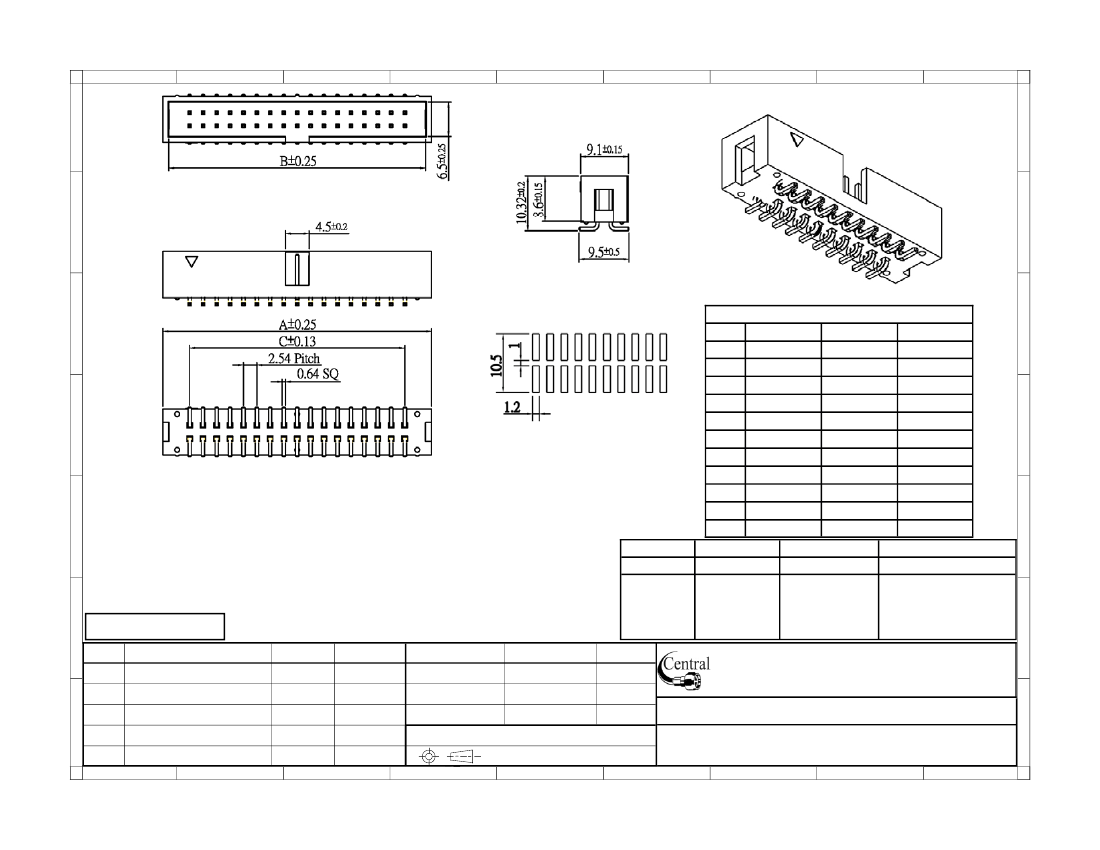
Board Connector, 34 Contact(s), 2 Row(s), Male, Straight, 0.1 inch Pitch, Surface Mount Terminal, Receptacle
| Parameter Name | Attribute value |
| Is it Rohs certified? | conform to |
| Objectid | 304489620 |
| Reach Compliance Code | unknown |
| ECCN code | EAR99 |
| YTEOL | 0 |
| Other features | ROHS COMPLIANT |
| body width | 0.358 inch |
| subject depth | 0.406 inch |
| body length | 2 inch |
| Body/casing type | RECEPTACLE |
| Connector type | BOARD CONNECTOR |
| Contact to complete cooperation | AU ON NI |
| Contact completed and terminated | Tin (Sn) - with Nickel (Ni) barrier |
| Contact point gender | MALE |
| Contact material | BRASS |
| contact mode | RECTANGULAR |
| Contact resistance | 10 mΩ |
| Contact style | SQ PIN-SKT |
| DIN compliance | NO |
| Dielectric withstand voltage | 1000VAC V |
| Durability | 1000 Cycles |
| Filter function | NO |
| IEC compliance | NO |
| Insulation resistance | 5000000000 Ω |
| insulator material | POLYAMIDE |
| JESD-609 code | e3 |
| MIL compliance | NO |
| Plug contact pitch | 0.1 inch |
| Match contact row spacing | 0.1 inch |
| Mixed contacts | NO |
| Installation method | STRAIGHT |
| Installation type | BOARD |
| Number of connectors | ONE |
| PCB row number | 2 |
| Number of rows loaded | 2 |
| Maximum operating temperature | 125 °C |
| Minimum operating temperature | -55 °C |
| PCB contact pattern | RECTANGULAR |
| PCB contact row spacing | 5.7404 mm |
| Plating thickness | 10u inch |
| polarization key | POLARIZED HOUSING |
| Rated current (signal) | 3 A |
| Guideline | UL |
| Terminal pitch | 2.54 mm |
| Termination type | SURFACE MOUNT |
| Total number of contacts | 34 |
 京公网安备 11010802033920号


