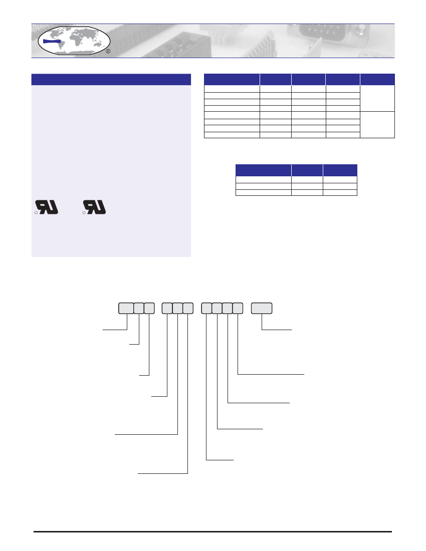
EEWORLDEEWORLDEEWORLD

Part Number

Search

8111-311-8133-03

Description
D Subminiature Connector, 9 Contact(s), Female and Female, Solder Terminal, Receptacle-receptacle
CategoryThe connector    The connector   
File Size368KB,2 Pages
ManufacturerECS
Websitehttp://www.ecsxtal.com/
Download Datasheet Parametric View All

8111-311-8133-03 Overview

D Subminiature Connector, 9 Contact(s), Female and Female, Solder Terminal, Receptacle-receptacle

8111-311-8133-03 Parametric

Parameter NameAttribute value
MakerECS
Reach Compliance Codeunknown
ECCN codeEAR99
Other featuresOTHER STACKING CONNECTOR: 9 CONTACTS, 1/E SHELL SIZE
Body/casing typeRECEPTACLE-RECEPTACLE
Connector typeD SUBMINIATURE CONNECTOR
Contact point genderFEMALE AND FEMALE
DIN complianceNO
empty shellNO
Filter functionNO
IEC complianceNO
insulator materialGLASS FILLED POLYBUTYLENE TEREPHTHALATE-POLYESTER
MIL complianceNO
Mixed contactsNO
Installation typeBOARD AND PANEL
OptionsGENERAL PURPOSE
Shell surfaceCHROMATE
Shell materialSTEEL
Housing size1/E
Termination typeSOLDER
Total number of contacts9
UL Flammability Code94V-0
Base Number Matches1
CC
S
SPECIFICATIONS
8100 Series D-Subminiature
Dual Port Connector
CONTACT POSITIONS
09 Plug
15 Plug
25 Plug
37 Plug
A
.666 [16.92]
.994 [25.25]
1.534 [38.96]
2.182 [55.42]
B
.984 [25.00]
1.312 [33.32]
1.852 [47.04]
2.500 [63.50]
C
1.213 [30.80]
1.543 [39.20]
2.091 [53.10]
2.732 [69.40]
D
.329 [8.36]
Insulator Material: Glass filled polyester, type PBT,
94 V-O, UL Rated.
Contact Material: Brass or Phosphor Bronze Alloy
Contact Plating: Gold and/or Tin over .000050” Nickel,
(See Contact Plating Options).
Shell: Steel, 100µ” Tin over 50µ” min. Nickel.
Clinch Nut: Brass, 100µ” min. Nickel Plated.
Boardlock: Brass, 100µ” min. Nickel Plated.
Screwlock: Brass, 100µ” min. Nickel Plated.
Current Rating: 3 amp at 30°C
Voltage Rating: 250 VAC/rms 60Hz
Contact Resistance: 20 m
max. At 1AMP DC.
Insulation Resistance: 1000 M
at 500 VDC.
Dielectric Withstand Voltage:
1500 V AC/rms 60Hz for 1 minute.
09 Rec.
15 Rec.
25 Rec.
37 Rec.
.642 [16.30]
.969 [24.60]
1.508 [38.30]
2.157 [54.80]
.984 [25.00]
1.312 [33.32]
1.852 [47.04]
2.500 [63.50]
1.213 [30.80]
1.543 [39.20]
2.091 [53.10]
2.732 [69.40]
.311 [7.90]
Dimensions are in inch [mm]
STACK HEIGHT
1
2
3
E
0.625 [15.88]
0.750 [19.05]
0.900 [22.86]
F
1.119 [28.42]
1.244 [31.60]
1.394 [35.41]
R
C
R
Recognized under the recognized component
Program of Underwriters Laboratories, Inc.
File Numbers: E146967 and E176234
81 X X
-
X X X
-
X X X X
-
XX
SERIES NO.
CONTACT TYPE (top)
1
= 9
2
= 15
3
= 25
4
= 37
03
=
05
=
10
=
20
=
30
=
PART NUMBERING
CONTACT PLATING
Mating
Gold Flash
Gold Flash
10µ” Au
15µ” Au
30µ” Au
Tail
Gold Flash
100µ” SnPb
100µ” SnPb
100µ” SnPb
100µ” SnPb
CONTACT TYPE (bottom)
1
= 9
2
= 15
3
= 25
4
= 37
SHELL PLATING
1
= Tin (Standard)
2
= Nickel
3
= Chromate
CONNECTOR TYPE
1
=
2
=
3
=
4
=
Plug / Plug
Plug / Receptacle
Receptacle / Recptacle
Receptacle / Plug
INSULATOR COLOR
1
= Black (Standard)
2
= Blue
3
= White
STACK HEIGHT
DIMENSION
“E”
1
= 0.625” [15.88 mm]
2
= 0.750” [19.05 mm]
3
= 0.900” [22.86 mm]
BOARD MOUNTING OPTIONS
1
= L-Shape Support
2
= Dual Arrowhead Boardlock
3
= Quad Arrowhead Boardlock
FLANGE MOUNTING OPTIONS
1
=
2
=
3
=
4
=
5
=
6
=
7
=
8
=
ø .120” [3.05 mm] Hole
#4-40 Threaded Hole
#4-40 Threaded Hole With #4-40 UNC Screwlock Installed
#4-40 Threaded Hold With #4-40 UNC Screwlock Bulk-Packed
M3 Thread Hole
M3 Thread Hole With M3 Screwlock Installed
M2.6 Thread Hole
M2.6 Thread Hole With M2.6 Screwlock Installed
CONNECTOR VERSION
1=
Dual Port
WWW.ECSCONN.COM
Embedded 6-20130201
One day, I saw the prototype of the abs function: int abs(int n) {return n0?-n:n; }It’s that simple, hahaha. If you haven’t seen it, you might not think it’s so simple, or you have never thought about...
zhaozhi0810 ARM Technology
MCP2517 (SPI to CAN) debugging record
1. Reasons for debugging: The project requires four CAN channels, but the MCU used is STM32F105, which only has two channels. CAN, so we use the Microchip SPI to CAN chip - MCP2517. During the debuggi...
RCSN stm32/stm8
ARES 4-layer board blind hole export Gerber problem
I have a question for you all. I made a 4-layer board with blind via inner 2 - TOP, but the exported Gerber file shows BOTT-TOP, and both are connected to Bott's GND. What's going on?...
mongolia_liu PCB Design
Why
I will work hard!!!!...
jamingtam Talking
LVDS input and output issues
According to the LVDS principle, when a differential signal needs to be sent, an LVDS differential signal transmitter should be used. The LVDS output differential signal should have two paths, IN+ and...
eeleader-mcu FPGA/CPLD
Autocad Antivirus
Is Autocad antivirus software useful?...
younha Embedded System

EEWorld
subscription
account

EEWorld
service
account

Automotive
development
circle

Robot
development
community

Index Files: 2233  1533  1276  1519  399  45  31  26  9  58 
Datasheet   0 1 2 3 4 5 6 7 8 9 A B C D E F G H I J K L M N O P Q R S T U V W X Y Z
Room 1530, 15th Floor, Building B, No. 18 Zhongguancun Street, Haidian District, Beijing Telephone: (010) 82350740 Postal Code: 100190
Copyright © 2005-2026 EEWORLD.com.cn, Inc. All rights reserved 京ICP证060456号 京ICP备10001474号-1 电信业务审批[2006]字第258号函 京公网安备 11010802033920号