# USB Amperemeter
> ##### My USB Amperemeter Project
## Regarding the structural design
, only the PCB board is used as its appearance. After all, it is only for learning
! [image-20220816134202049](https://s2.loli.net/2022/08/16/FLGloteWXwHcM45.png)
## Regarding the circuit design
, the official case of the training camp open source is used without any modification. The 0603 package is replaced with 0402 (just because there are more original parts in this package)
## The main control
N32G430C8L7 microcontroller product adopts a high-performance 32-bit ARM Cortex™-M4F core, integrated with a floating-point unit (FPU) and digital signal processing (DSP), and supports parallel computing instructions. The maximum operating frequency is 128MHz, integrated with up to 64KB on-chip encrypted storage Flash, and supports multi-user partition permission management, and supports 16KB of embedded SRAM. It has an internal high-speed AHB bus, two low-speed peripheral clock buses APB and bus matrix, supports 40 reusable I/Os, provides rich high-performance analog interfaces, including 1 12-bit 4.7Msps ADC, supports 16 external input channels and 3 internal channels, and provides a variety of digital communication interfaces, including 4 U(S)ARTs, 2 I2Cs, 2 SPI/I2Ss, and 1 CAN 2.0B communication interface. The N32G430C8L7 microcontroller product can work stably in the temperature range of -40°C to +105°C, with a supply voltage of 2.4V to 3.6V, and provides a variety of power consumption modes.
Not many resources are used in this case, and the internal clock is open source to meet the design requirements, so there is no need for an external clock circuit. It should be noted that each power pin of the chip needs to be connected to an additional 100nF external filter capacitor, and the chip's 1 pin needs to be connected to an additional 4.7uf filter capacitor.

## Reset circuit, BOOT circuit
Since this design is to adapt to the public version housing, the reset circuit and BOOT circuit are not designed with buttons, and two solder joints are used as short circuits.


## The programming interface
chip supports multiple programming methods, such as the common ST-Link, USB-TTL, Jlink and other programmers on the market. In the case, the corresponding interface has been led out with a 2.54 spacing pin for programming.

## Voltage conversion
Although the MCU used in this case supports a maximum voltage of 5V, it takes into account the possible unstable voltage factors on the USB voltage or other voltages

## Current sampling, USB input/output
### USB input/output
The USB input end uses a Type-A male plug and inputs a voltage of 5V. This interface supports a maximum output of 3A. If it is larger, it will get a little hot. It is recommended not to exceed 3A of current. If you need to use a larger current, please replace the Type-A male plug.

The USB output end uses a 4P sinker female socket. In order to adapt to the public version shell, the maximum rated current of this female socket is 1.5A, and the actual measured current is 2.5A, but it is not suitable for long-term work under this current. If you need to use a larger current, please replace it yourself.

### Current Sampling The current
sampling part is the INA199B1DCKR current sensing amplifier, (also known as a current sensing amplifier) which is commonly used in overcurrent protection, precision current measurement for system optimization, or closed-loop feedback circuits. This series of devices can sense the voltage drop across the shunt resistor at a common-mode voltage of –0.3V to 26V independent of the power supply voltage. There are three fixed gains to choose from: 50V/V, 100V/V, and 200V/V. This series of devices uses a zero-drift architecture with low offset, so the maximum voltage drop across the shunt resistor can be kept to a minimum of 10mV full scale when performing current sensing. The parameters are as follows:
- Common mode range: –0.3V to 26V
- Offset voltage: ±150μV (maximum)
- Supports 10mV full-scale shunt voltage drop
- Quiescent current: 100μA (maximum)
### Sampling resistor selection
Inserting a low-resistance detection resistor in series in the current path will form a small voltage drop, which can be amplified and treated as a signal proportional to the current. However, depending on the specific application environment and the location of the detection resistor, this technology will pose different challenges to the detection amplifier. Generally, the resistance value of the sampling resistor is below 1 ohm, which is a milliohm-level non-inductive resistor, but some resistors have requirements such as sampling voltage, and large resistance value resistors must be selected, but the resistance base is large and the error is large. In this case, it is necessary to select a high-precision non-inductive resistor (which can reach 0.01% accuracy, that is, one ten-thousandth accuracy) to make the sampled data very reliable. The temperature coefficient of the ultra-low resistance value resistors (0.0005 ohms, 2 milliohms, 3 milliohms, 10 milliohms, etc.), SMD alloy resistors, high-power resistors (20W, 30W, 35W, 50W, 100W) and other products is plus or minus 5PPM.
#### Sampling method
- This sampling uses **low-side sampling**, that is, the sampling resistor is connected to the GND loop. This design can calculate the complete differential, follow, amplify, and output when the differential signal is sent to the op amp. If high-side sampling is used, that is, the sampling resistor is placed at the high position between the power supply and the load, although this placement not only eliminates the ground interference generated in the low-side detection scheme, but also detects the accidental short circuit from the battery to the system ground, **high-side detection** requires the detection amplifier to handle a common-mode voltage close to the power supply voltage. This common-mode voltage value range is very wide, ranging from the level required to monitor the processor core voltage (about 1V) to hundreds of volts commonly seen in industrial, automotive, and telecommunications applications. Application examples include typical laptop battery voltages (17 to 20V), 12V, 24V, or 48V batteries in automotive applications, 48V telecommunications applications, high-voltage motor control applications, current detection for avalanche diodes and PIN diodes, and high-voltage LED backlights. Therefore, an important advantage of high-side current detection is that the detection amplifier has the ability to handle larger common-mode voltages.
Therefore, the current sampling method of sampling resistor plus op amp is best performed at the low end. Although low-end sampling will affect the signal ripple due to common ground interference, compared to high-end sampling, the solution is simple, low-cost and highly reliable.
Note: If the stock of INA199B1DCKR is insufficient, you can replace it with INA199A3DCKT. It should be noted that the magnification of INA199B1DCKR is 50. If you use other magnifications, you need to modify the program calibration again.
> Use INA199A3DCKT with a gain of 200

## Voltage sampling
The voltage sampling part is composed of a voltage divider circuit composed of two resistors. Its principle is the knowledge of resistor series voltage division. The typical circuit is as follows:


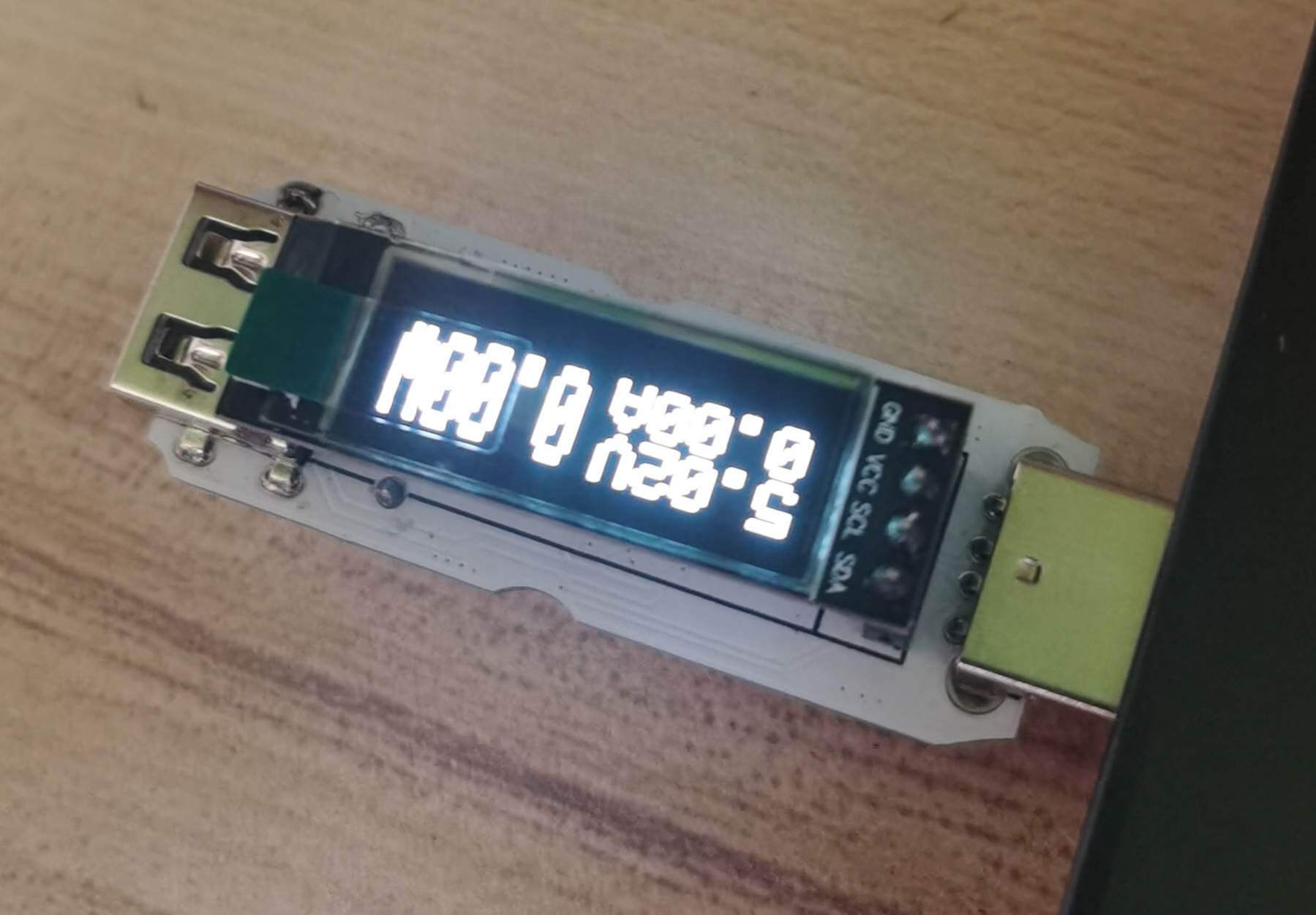
## Display part The
display part uses a 0.91-inch 4P white OELD screen module and adopts IIC communication, with clear display effect.

Design display effect

# Software Description
## Compilation parameters
- Compiler: ARM Compiler version 5 (-O0)
- MDK version: 5.31
- Debugger: ST-Link V2
## Note:
If the sampled voltage or current is inaccurate, you can modify the values of `VOLTAGE_FACTOR` and `CURRENT_FACTOR` in the `main.c` file according to the actual values. The specific calculation formula is:
```
VOLTAGE_FACTOR = actual voltage / displayed voltage
CURRENT_FACTOR = actual current / displayed current
```
> This is the fast charging version. There are some bugs in the DC power supply part. I don’t know if it is a problem with my wiring or the circuit itself. I will modify the wiring later to see if the output voltage can be normal.


 京公网安备 11010802033920号

 5082-7666-GF100


