Note: * is a required field,
please fill it out during the registration stage↓
* 1. Project function introduction
It can measure the voltage, current and power during operation.
* 2. Project features
0.91-inch OLED screen, with clear and compact display effect;
PCB board is adapted to the public version housing;
low-resistance sampling resistor is used to prevent excessive internal resistance from affecting the USB power supply efficiency;
Maximum voltage measurement support: 6V
Maximum measurement current: 2.8A
Support power display
* 3. Hardware part
Main control:
N32G430C8L7 microcontroller product adopts high-performance 32-bit ARM Cortex™-M4F core, integrated floating-point unit (FPU) and digital signal processing (DSP), and supports parallel computing instructions. The highest working frequency is 128MHz, integrated up to 64KB on-chip encrypted storage Flash, and supports multi-user partition authority management, and supports 16KB embedded SRAM. It has an internal high-speed AHB bus, two low-speed peripheral clock buses APB and bus matrix, supports 40 reusable I/Os, provides rich high-performance analog interfaces, including a 12-bit 4.7Msps ADC, supports 16 external input channels and 3 internal channels, and provides a variety of digital communication interfaces, including 4 U(S)ARTs, 2 I2Cs, 2 SPI/I2Ss, and 1 CAN 2.0B communication interface. The N32G430C8L7 microcontroller product can stably operate in a temperature range of -40°C to +105°C, with a supply voltage of 2.4V to 3.6V, and provides a variety of power consumption modes.
Master

reset circuit

BOOT selection

serial port and debug interface

current sampling circuit
The current sampling part is the INA199B1DCKR current sensing amplifier (also called current sensing amplifier), which is often used for overcurrent protection, precision current measurement for system optimization, or closed-loop feedback circuits. The devices sense the voltage drop across a shunt resistor at a common-mode voltage of –0.3V to 26V, independent of the supply voltage. Three fixed gains are available: 50V/V, 100V/V, and 200V/V. The devices use a zero-drift architecture with low offset, so the maximum voltage drop across the shunt resistor is kept to a minimum of 10mV full-scale when sensing current. The parameters are as follows:
Common-mode range: –0.3V to 26V
Offset voltage: ±150μV (maximum)
Supports 10mV full-scale shunt voltage drop
Quiescent current: 100μA (maximum

Buck circuit

Voltage sampling

Current sampling, USB input/output
USB input/output
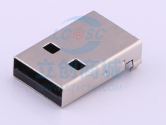
The USB input uses a Type-A male connector, which inputs a 5V voltage. This interface supports a maximum output of 3A. If it is larger, it will get a little hot. It is recommended not to exceed 3A of current. If you need to use a larger current, please replace the Type-A male connector.
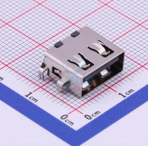
The USB output uses a 4P sinker female socket. In order to adapt to the public version housing, the maximum rated current of this female socket is 1.5A. The actual measurement is 2.5A, but it is not suitable for long-term operation at this current. If you need to use a larger current, please replace it yourself.
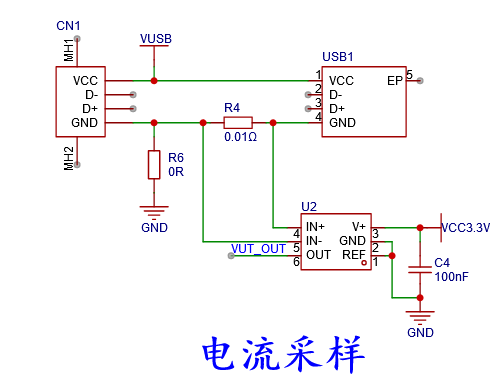
Current sampling
The current sampling part is the INA199B1DCKR current sensing amplifier (also known as a current sensing amplifier), which is often used for overcurrent protection, precision current measurement for system optimization, or closed-loop feedback circuits. This series of devices can sense the voltage drop across the shunt resistor at a common-mode voltage of –0.3V to 26V independent of the power supply voltage. There are three fixed gains to choose from: 50V/V, 100V/V, and 200V/V. This series of devices uses a zero-drift architecture with a low offset, so the maximum voltage drop across the shunt resistor can be kept at a minimum of 10mV full scale when current sensing is performed. The parameters are as follows:
Common mode range: –0.3V to 26V
Offset voltage: ±150μV (maximum)
supports 10mV Full-scale shunt voltage drop
Quiescent current: 100μA (maximum)
Sampling resistor selection
Inserting a low-resistance detection resistor in series in the current path will form a small voltage drop, which can be amplified and treated as a signal proportional to the current. However, depending on the specific application environment and the location of the detection resistor, this technology will pose different challenges to the detection amplifier. Generally, the resistance value of the sampling resistor is below 1 ohm, which is a milliohm-level non-inductive resistor, but some resistors have requirements such as sampling voltage, and large resistance value resistors must be selected, but the resistance base is large and the error is large. In this case, it is necessary to select a high-precision non-inductive resistor (which can reach 0.01% accuracy, that is, one ten-thousandth accuracy) to make the sampling data very reliable. Ultra-low resistance value of the patch Resistors (0.0005 ohms, 2 milliohms, 3 milliohms, 10 milliohms, etc.), SMD alloy resistors, high-power resistors (20W, 30W, 35W, 50W, 100W) and other products have a temperature coefficient of plus or minus 5PPM.
Sampling method
This sampling uses a low-side sampling method, that is, the sampling resistor is connected to the GND loop. This design can calculate the complete differential, follow, amplify, and output when the differential signal is sent to the op amp. If high-side sampling is used, that is, the sampling resistor is placed at a high position between the power supply and the load, although this placement method not only eliminates the ground interference generated in the low-side detection scheme, but also detects accidental short circuits from the battery to the system ground, but high-side detection requires the detection amplifier to handle a common-mode voltage close to the power supply voltage. This common-mode voltage value range is very wide, ranging from the level required to monitor the processor core voltage (about 1V) to hundreds of volts commonly seen in industrial, automotive, and telecommunications applications. Application cases include typical laptop battery voltage (17 to 20V), 12V, 24V or 48V batteries in automotive applications, 48V telecommunications applications, high-voltage motor control applications, current detection for avalanche diodes and PIN diodes, and high-voltage LED backlights. Therefore, an important advantage of high-side current detection is that the detection amplifier has the ability to handle large common-mode voltages. Therefore, the current sampling method of sampling resistor plus op amp is best performed at the low end. Although low-end sampling will affect the ripple of the signal due to common ground interference. But compared to the high end, the solution is simple, low cost and high reliability.
Note: If the stock of INA199B1DCKR is insufficient, you can replace it with INA199A3DCKT. It should be noted that the magnification of INA199B1DCKR is 50, and the program calibration needs to be modified again if other magnifications are used.
OLED display module
oled display uses iic communication, it costs more than 12 yuan on Taobao, the quality is very good, very good

*4. Software part
compiler: ARM Compiler version 5 (-O0)
MDK version: 5.31
debugger: ST-Link V2
* 5. Demonstrate your project and record it into a video and upload it for


more details: https://diy.szlcsc.com/posts/d76d9cb41705430e9a54e7a5feed07a5


 京公网安备 11010802033920号

 LF12.0MHZIQXO-70IC


