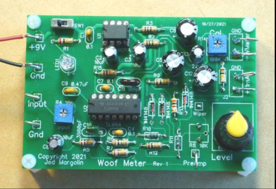
Woof Meter is used to test subwoofer speakers. It contains a low-frequency preamplifier, a precision full-wave rectifier and a DC filter. Woof Meter is used to test subwoofer speakers to measure their Thiele-Small (TS) parameters. These parameters are necessary in order to correctly design the loudspeaker cabinet. Sometimes you may not have the TS parameters for the subwoofer speaker you want to use, and sometimes the TS parameters provided by the speaker manufacturer are wrong. To measure the TS parameters of a subwoofer, you need a sensitive voltmeter with good low frequency response. Your voltmeter may not have a good enough low frequency response to test the subwoofer. The Woof Meter contains a low-frequency preamplifier, a precision full-wave rectifier and a DC filter. It has a voltage output that can be read with any standard DC voltmeter. It also has a current output for use with an analog 1mA meter. The Woof Meter is a companion product to my precision low frequency signal generator, which generates a user-selectable signal from 10Hz to 90Hz with a resolution of 0.1Hz. Frequency is displayed on 16x2 LCD. You can use a 9V transistor battery for power. This makes the Woof Meter float so it is not affected by ground loops. The battery lasts a long time. To use the Real Pot, do not fill the trimpot R8. Install a real pot in the hole labeled "Real Pot." You need to connect real pots to the traces on the board. External terminals Connect to the external terminals of R8 pad. Since the wiper pin (center pin) of R8 is difficult to wire when mounting a real potentiometer, I took it out to a separate pad labeled "Wiper". There are two outputs. One for DC voltmeters (analog or digital). The other one is for the 1mA analog meter. I am using a meter I bought on eBay called: Analog Panel Meter 1mA DC 0-1mA 85C1 Meter. The board skill level is: Intermediate. Make sure to use a temperature-controlled soldering iron. The temperature I used was 340 degrees Celsius. And don't breathe solder fumes. If you don't have a fume hood, use a fan to blow the solder fumes away. How to use: 1. Connect the precision low frequency signal generator to the subwoofer through a 100 ohm resistor, which converts the voltage output of the signal generator into a current source. (100 ohms is much louder than a 4 ohm or 8 ohm speaker.) 2. Connect the speaker terminals to the bass meter input. 3. Adjust the input potentiometer R4 so that the preamplifier does not clip. 4. Using an analog 1mA meter or voltmeter connected to the voltage output, adjust Level pot R8 (or Real Pot if you are using a Real Pot) to obtain the desired output. If you are using both, you should first adjust the level of the 1mA meter and then adjust the trimpot R14 to produce a convenient reading on the voltmeter. This way you can use an analog meter for rough readings and a voltmeter (assuming it's a digital meter) for fine readings. Testing of subwoofer speakers and design of subwoofer cabinets are beyond the scope of this article. I recommend the following: 1. For testing subwoofer speakers for Thiele-Small (TS) parameters: Measuring Speaker Parameters by Rod Elliott https://sound-au.com/tsp.htm Basically, you: A . Connect the precision low frequency signal generator to the subwoofer speaker via a 100 ohm resistor. This makes the output a current source. You will need a sensitive voltmeter with good low frequency response, or you can use a Woof Meter which contains a low frequency preamplifier, precision full wave rectifier and DC filter. It has a voltage output that can be read by any standard DC meter. It also has a current output for use with an analog 1mA meter. For precision low frequency signal generator project, please click here. b. Find the free air resonant frequency of the speaker. This is where the voltage across the speaker is greatest. C. Find the higher and lower frequencies where the response drops by 3dB. That is 0.707 of the resonant voltage (or current). d. Add 25 grams of weight to the speaker cone. A US nickel weighs exactly 5.0000 grams, so 5 nickels are attached to the cone. (Use masking tape.) e. Repeat the above test: find the resonant frequency and the two -3dB frequencies. F. There are other things you need to measure (using a standard multimeter). G. Plug your measurements into the correct formula and you will get the TS parameters. Then you can design the cabinets. 2. Subwoofer enclosures for designing vented, sealed and custom bandpass enclosures: https://www.ajdesigner.com/speaker/. See also: http://www.mh-audio.nl/Loudspeakers.html#top I have published more information (that you need) and more pictures on my website: www.jmargolin.com/newprojects /woof-meter/woof-meter.htm Happy Subwoofer tests and builds whether you use this analog meter or a DVM.


 京公网安备 11010802033920号

 TK11222BMIB


