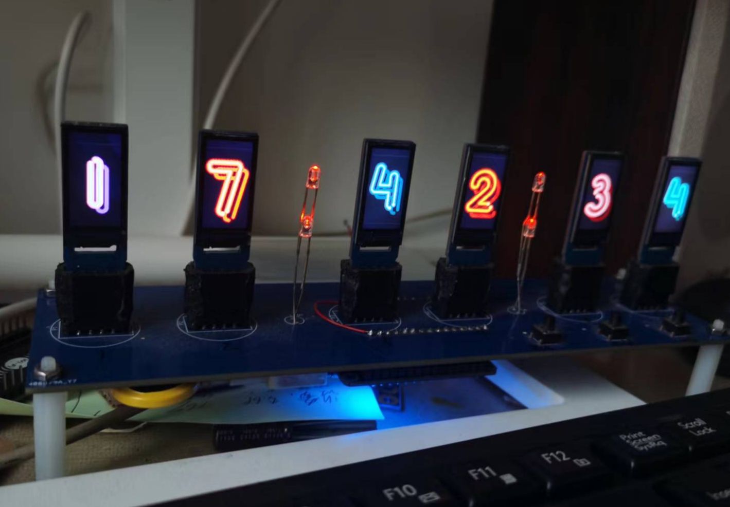
Main control: esp8266
Principle: 0.96tft adopts spi transmission mode, CS low level is active, esp8266 has too few pins, so a peripheral chip is needed for pin expansion. TM1650 was chosen to expand the control screen CS pin to select screen refresh, but please note that since TM1650 also has a keyboard scanning function, when each segment outputs a high level, there will be a low level output of about 1 millisecond in the middle, which will cause The timing is chaotic, so several capacitors must be connected for filtering (c8~c13). These capacitors must not be omitted. At the same time, due to the addition of these capacitors, the keyboard scanning function is useless. . . At this time, esp8266 only had one A0 left, so I thought of a way to add resistors (r1~r3) with different resistances to the three buttons to check the input voltage to achieve button scanning (I only discovered this problem after finishing the board. Therefore, there are flying wires in the sample video, and the published schematic diagram and PCB diagram have been modified. However, I transferred the project from the standard version, so it is best to check the PCB diagram again when using it).
I added a ds3231 as a clock chip, but later I found that it seems that it can be used without it. I can just use the esp8266 as the RTC. In order to make the best use of everything, I used it in my program. If it is not used, you can modify it yourself.
The music chip is DH8058, which is used for different alarms (the program has not been written yet, but the chip driver has been written).
Program: It is written using Arduino IDE, and the screen driver has been rewritten by itself, which greatly improves the refresh rate. However, I have only written the time display and screen switching so far. es8266 often restarts inexplicably. I have tried many methods but have not been able to solve it. I really don’t know how to do it. If you are interested, please help me improve the program.
In addition, the pictures need to be uploaded to the flash of esp8266 in advance. They must be 80*160, 24-bit bmp pictures. There are 4 groups in the attachment. If you need other styles, please upload them yourself. See the data folder. After testing, the flash of the esp8266 module can store up to 4 groups of pictures.

