Project Description:
This programmable ammeter supports current protection, allowing real-time monitoring of supply voltage and current, and providing real-time current limit indication. It features rapid response, timely protection of downstream load circuits, quick adjustment, and ease of use.
Open Source License
: This project is licensed under the GPL 3.0 open source license and can be freely copied, modified, and distributed.
Project Features:
1. Supports fast charging power supply; USB supply voltage range is 5-35V, offering a wide operating voltage range.
2. Programmable protection current is continuously adjustable from 20mA to 3000mA, with an adjustable trigger period and rapid response.
3. Adjustable tolerance; small fluctuations can be set to allow for small amplitude fluctuations.
4. Extremely fast response to high current; when the instantaneous current exceeds 1.2 times the set value, it will immediately disconnect the downstream circuit.
5. Source code is provided for easier optimization and improvement.
Project Attributes:
This project is being publicly released for the first time and is my original work. This project has not won any awards in other competitions.
Project Schedule
: 1. July 12, 2023: Project awarded, design scheme confirmed and commenced.
2. July 14, 2023: Hardware circuit design completed, PCB prototyping ordered.
3. July 18, 2023: PCB received, soldering and testing commenced . 4. July 28, 2023
: Program design completed, functional testing and video recording commenced . 5. July 30,
2023: Final filtering and optimization of sampled data for smoother display; overall production completed, awaiting acceptance.
6. July 31, 2023: Task acceptance and content optimization.
7. August 16, 2023: Code optimization and panel redesign.
8. September 7, 2023: The new panel prototype has arrived, and
the design principle has been resubmitted for review.
The overall design concept is as follows: The main goal is to implement a programmable ammeter. Firstly, it needs to display the current, and secondly, it needs programmable current protection. The requirements are not complex, but considering it's an intermediate component in a charger, there might be QC (Quality Control) and higher voltage requirements, necessitating support for a wide voltage supply range. Therefore, a DC-DC step-down circuit is used, with a supply voltage range of 5-20V. A two-stage regulation is employed: the DC-DC converter first steps down the voltage to 5V, and then an LDO further steps it down to 3.3V. This significantly improves the stability of the MCU's power supply voltage, resulting in a smoother power supply and improved ADC sampling stability.
1. Power Supply

Circuit: Power is directly supplied from the USB. A DC-DC step-down chip JW5015A is used to step down the input voltage to 5V, and then an LDO SK6014 is used to regulate it to 3.3V. A resettable fuse and ESD protection are used for downstream protection to ensure the safety of downstream circuits in case of problems with the upstream DC circuit.
The DC-DC step-down chip currently used is the best one I've found so far, mainly because it supports a wide range and provides very stable output at low voltages. In actual testing, with an input voltage of 5.12V, the measured output reached 5.08V (the error value may be related to the accuracy of the FB feedback terminal), with almost no voltage drop. The output voltage is also very stable throughout the entire power supply range.
2. Output Control and Current Sampling Circuit: The

output control circuit uses a PMOS WSD30L20DN from Micro-Signal. This PMOS supports a maximum voltage of 30V and a current of 20A (with good heat dissipation), and is affordable, with a compact DFN 3*3 package.
Simple working principle analysis: PMOS conducts at low levels, so initially, R3 applies a high level to the gate (G) of Q2, and Q2 is off by default. When needed, a high level is input via VBUS_CTRL, turning on Q1, which pulls down the gate voltage of Q2, turning on Q2 and supplying power to the subsequent stage, thus completing the switching process. Since the Vgs voltage of Q2 is 20V, a voltage divider is used to protect the MOSFET from excessively high Vgs voltage and damage.
Current sampling uses an INA180A3, which has a gain of 100, meaning it amplifies small voltages by a factor of 100, facilitating sampling and improving accuracy. A 3.3V ESD is also used at the sampling output to prevent high voltage from damaging the MCU.
3. USB voltage sampling:

Voltage sampling primarily uses resistors with 0.1% accuracy to improve sampling precision.
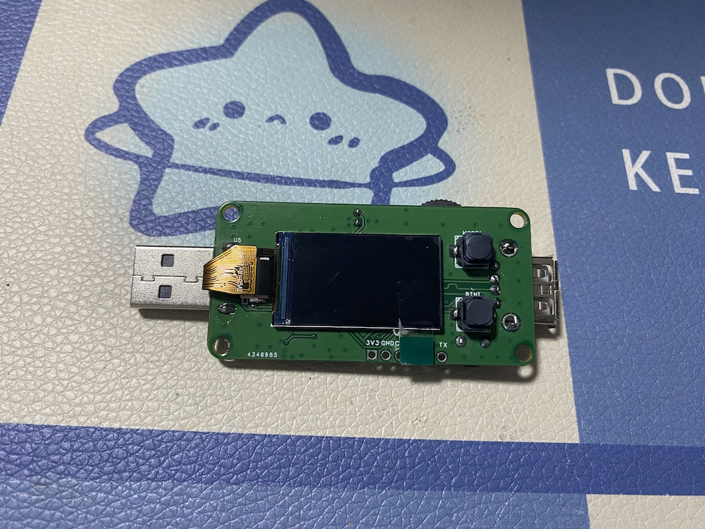
4. LCD ST7789 1.14-inch screen display circuit:

A 1.14-inch 8-pin screen is used here. This screen is readily available, inexpensive, and widely used. An additional backlight circuit is added to facilitate PWM brightness control.
5. Button Circuit:
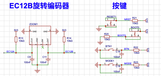
This circuit uses two buttons and a dial encoder. The buttons are made of soft silicone, providing a good tactile feel. The encoder used is an EC12B dial encoder, which is not very common on Taobao, but the price is low at only 4 yuan. However, the shipping cost is slightly high, so buying a few at once is still acceptable.
The reason for mentioning the buttons separately is that you shouldn't skimp on the hardware anti-shake capacitors connected in parallel with the buttons. These capacitors play a very important role in anti-shake, so don't think they're useless and skip soldering them.
6. Passive Buzzer Driver Circuit:
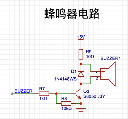
You need to buy a passive buzzer, not an active one, because this circuit uses PWM to drive the sound.
7. Main Control Circuit:

The main control uses the N32G430C8L7 from National Technology, with 64K Flash and 16K SRAM. It can be purchased from LCSC Mall or Taobao, and it's considered a good value for money among domestic chips.
Software Description
1. Development Environment:
The software is developed using Keil 5.36, which is a relatively stable version. The N32G430C8L7 SDK version used is 1.1.0.
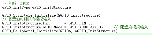
2. ADC Sampling:
DMA is used for ADC sampling here, reducing MCU involvement and offering high speed and efficiency.
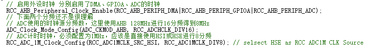
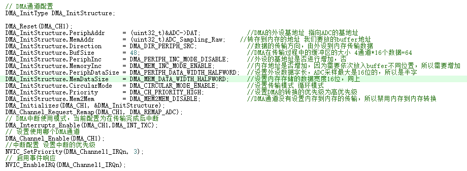
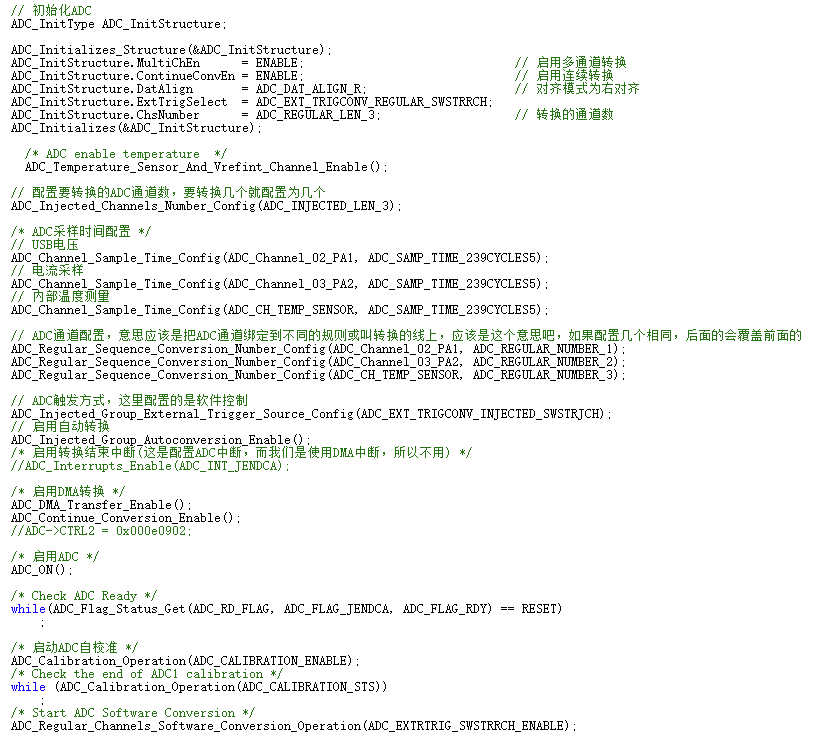
Three channels are sampled: voltage, current, and the built-in temperature sample, although the temperature is not used. 16x oversampling is used to reduce ADC sampling drift and improve sampling accuracy, but this increases sampling time.

The interrupt occurs after the DMA sampling transfer is complete; an interrupt is triggered after each set of data is sampled, allowing for data processing.
Current limiting protection is also handled here, prioritizing response and ensuring fast protection of downstream circuits.
3. Millisecond Timer:
High-precision time is crucial in program design, so enabling a high-precision clock is essential. Avoid tick timers, as they lack precision and consume MCU time and resources. In this program, the millisecond timer is involved in almost all modules and is particularly important.
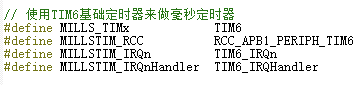
Since the timer is simply a time counting function, the basic timer TIM6 is sufficient, and there's no need to waste resources on other general-purpose or advanced timers.

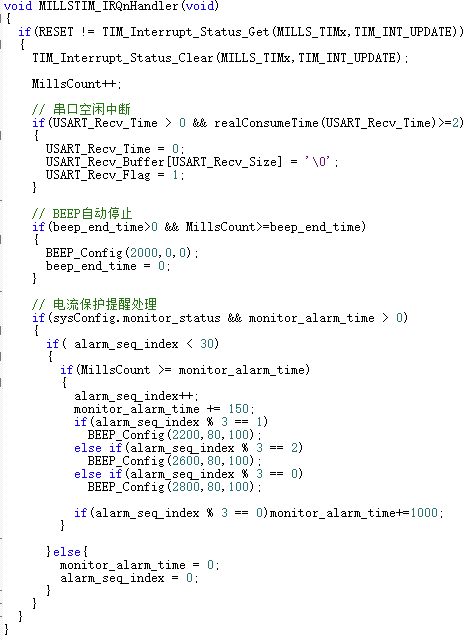
In the timer update interrupt, besides time counting, additional functions are implemented:
1) Because the N32G430 serial port lacks an idle interrupt, a custom idle interrupt must be implemented to enable variable-length serial port reception;
2) An automatic buzzer stop function is implemented with a timer marker; it automatically stops after a specified time, eliminating the need for additional check code;
3) Different sound processing is handled here after entering current limiting protection, eliminating the need for a delay. Design Considerations
for Physical Demonstration: It is recommended to use 0.1% accuracy resistors for sampling resistors R11 and R12, with a minimum of 1% accuracy, otherwise, the voltage sampling accuracy will be affected. Other demo videos: Demo videos can be uploaded as attachments. Attachments are limited to a maximum file size of 50MB. Files larger than 50MB can be hosted on other cloud storage services or video websites; simply include the link here. Project attachments: Entries participating in the event must upload the relevant program attachments to an open-source platform or personal code storage cloud. Attachments are limited to a maximum size of 50MB (please do not upload to the LCSC workspace, as there are restrictions). Attachments have size limitations. You can view high-definition videos on Bilibili: #SparkProject# Programmable Ammeter_Demo Video: https://www.bilibili.com/video/BV19u4y1k7Jf/ #SparkProject# Programmable Ammeter_ISP Download Demo: https://www.bilibili.com/video/BV1yV4y1i7iF/ Purchase links for several components not available at LCSC (you can search for them yourself; this is just to reduce search hassle): EC12B 1510001A: DC-DC Chip JW5015A: https://item.taobao.com/item.htm?spm=a1z09.2.0.0.16852e8dHDosl1&id=622986639277&_u=7otnt32a9b 1.14-inch ST7789 8P Connector Screen: https://item.taobao.com/item.htm?spm=a1z09.2.0.0.16852e8dHDosl1&id=704422089732&_u=7otnt3c943 https://item.taobao.com/item.htm?spm=a1z09.2.0.0.67002e8dEAHchZ&id=671435982680&_u=6otnt31283 For other components, it is recommended to prioritize purchasing from LCSC and find some reliable online stores to prevent problems with replicas.


 京公网安备 11010802033920号

 VSMP20181K5000TCR0.2CBW


