Video Link:
My video is this
quick jump
1. Project Introduction
2. Project Functions
3. Project Parameters
4. Hardware Description
5. Microcontroller Program Description
6. Mobile APP Program Description
7. My GitHub Repository
8. Precautions
9. Assembly Process
10. Physical Object Image
Project Introduction
This project is a quadruped robot design based on the ESP32 microcontroller. From project creation to writing this article, it took a total of 7 days, starting from the existing gait.
Main Functions: Executes 16 different actions, coordinated with facial expressions. It can be remotely controlled via UDP through a mobile APP,
using AP mode or STAION mode. It can also be configured for network access via the mobile app without opening or modifying the program.
It has OTA over-the-air download function for convenient updates. The OTA URL can be written through the mobile app, and the OTA update requires bin files hosted on the Buffalo Cloud platform.
Project Functions
16 Robot Actions: Stand at attention, move forward, move backward, turn left, turn right, normal, lie down, sleep, doggy paddle, play dead, come here, surrender, hello, finger, surrender, dance.
Action or function commands can be transmitted directly to the microcontroller via UDP using a mobile app or NetAssist on a computer.
Function commands include: motion control, single servo control, PWM frequency control, network configuration, configuring the OTA update URL, switching the ESP32's WiFi mode, and triggering the OTA update program.
Action commands include: 16 basic actions, suspending and resuming RGB lighting tasks, displaying the local IP address, and displaying 9 emoticons in a polling manner.
A 0.96-inch OLED screen displays emoticons and prompts: 9 emoticons mapped to 16 actions, displaying the local IP address, indicating successful network configuration, displaying OTA update in progress, and showing the WiFi mode selection menu.
Two WS2812 chips are currently used for the lighting function.
Four buttons, EN, BOOT, Key1, and Key2, can be used together to switch WiFi modes and trigger OTA updates.
The OTA update function facilitates remote update downloads.
The project parameters
use a PCA9685 chip to control 8 servos and communicate with the microcontroller via I2C, saving pins and computing power.
The power supply design uses readily available charge/discharge modules, saving design time. The
four-legged connectors were purchased ready-made from Taobao. The
servo motors used are the cheapest and worst available, the SG90.
Hardware Specifications:
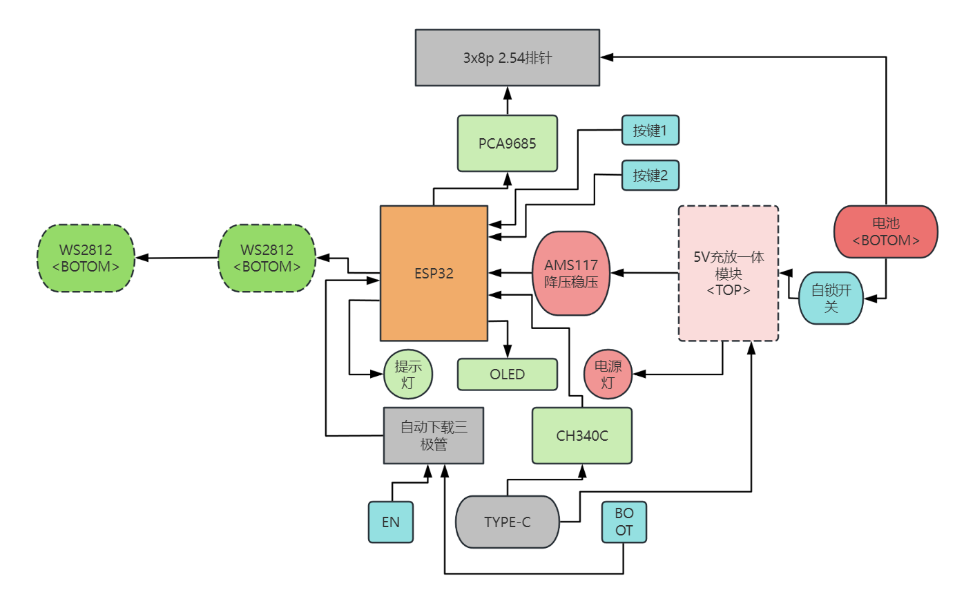
This project consists of the following parts: power supply, main control unit, servo motor control unit, button control unit, and functional components.
Hardware Connection Diagram :
Darker colors represent the bottom layer, lighter colors represent the top layer, and the lightest color represents something on top of the top layer.
Microcontroller Program Description:
Initially, I considered using Bluetooth for its convenient connection, easy microcontroller programming, and convenient mobile app development. However, it would be too large. Before enabling Bluetooth, the compiled code used 22% of the flash memory (default program allocation is 1.2MB). Enabling Bluetooth immediately increased the flash memory to 90%, making it difficult to write subsequent code. Therefore, I ultimately used UDP.
Arduino's built-in libraries are like this; using IDF would be much better.
This program uses a FreeRTOS multi-tasking architecture. Tasks communicate with each other using task notifications, including:
`void ota_task(void *param)
` // OTA task, which can be created by other tasks to trigger OTA updates; `
void udp_control(void *param)
` // UDP task, used to receive incoming commands, parse them, and notify other tasks to process them. It can also broadcast the local IP address, WiFi mode, and RGB status when starting the task, so that the microcontroller can receive and parse the commands even if it doesn't know the mobile app's IP address;
`void motion_task(void *param)
` // Servo control task, receives notifications from the UDP task and executes corresponding actions;
`void oled_task(void *param)
` // OLED control task, receives notifications from the UDP task and executes corresponding displays. It can also display a menu via buttons to notify UDP to restart and switch WiFi modes;
`void ws2812_task(void *param)
` // RGB lighting task, simply executes lighting tasks, which can be suspended or resumed by commands to switch RGB displays;
`void setup()` `
void loop()`
// In setup, we create the necessary tasks and initializations. Then, we delete tasks in loop to save memory.
OTA uses Buffalo Cloud servers for bin file hosting; you can refer to this blog for related tutorials.
Some complex processes have been written as classes; main.cpp contains the main flow.
Because this project was written quickly, it hasn't been aesthetically pleasing, so reading it might be a bit inconvenient.
For detailed program content and introductions, please see my GitHub repository. I'll probably write more detailed code features in the readme later.
I might add comments to the code later when I have time. I don't like writing many comments for such a small project; you can use an AI plugin in VSCode to help with comments. Currently, I'm using CodeGeeX; it's not particularly powerful, but it works quite well, and most importantly, it's free!
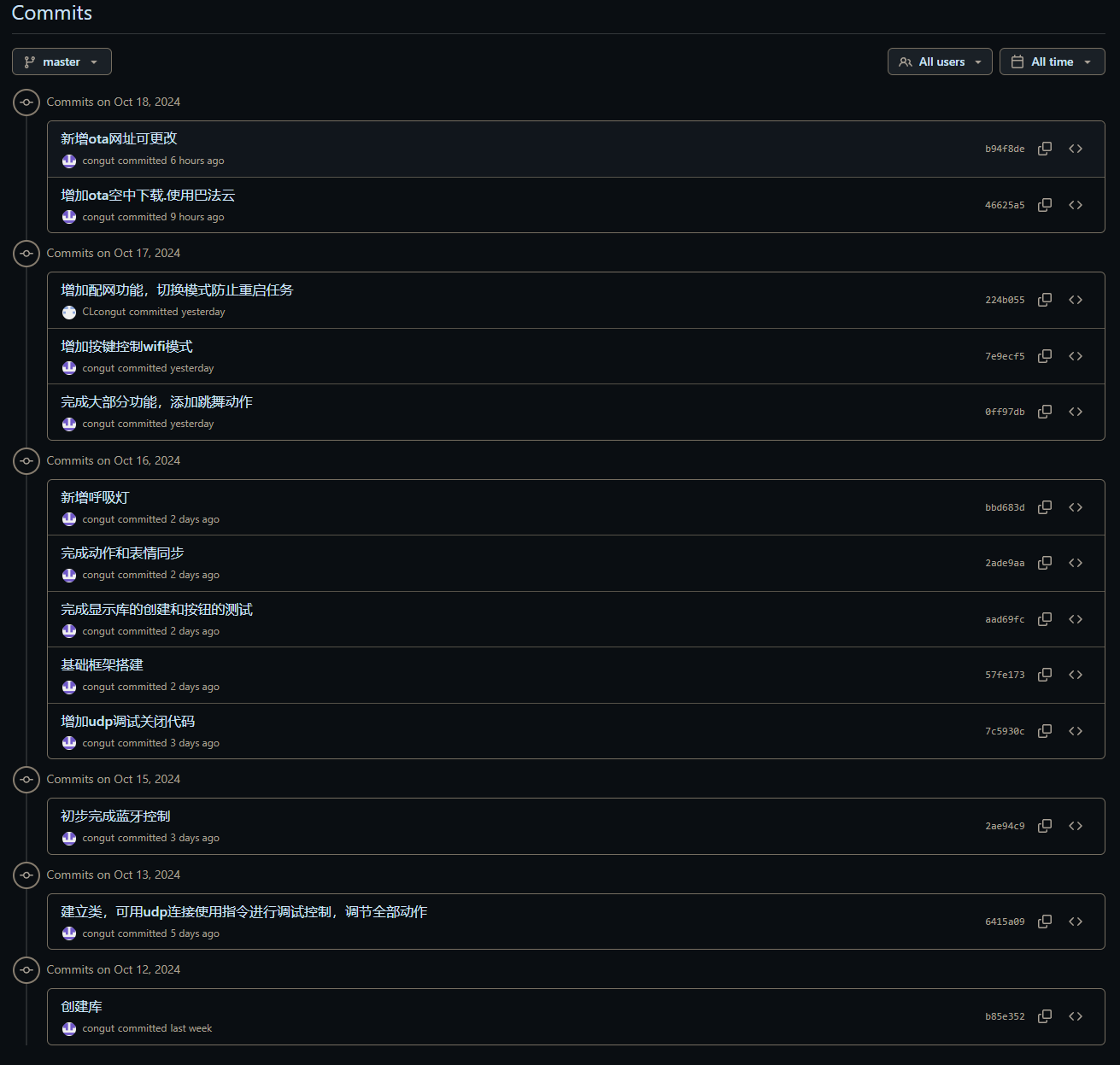
You can see from my commits that there aren't many; they're mostly for adding features, not much optimization. The AI2
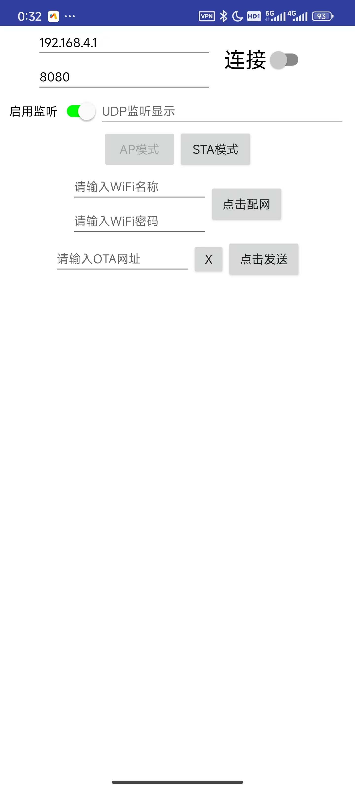
mobile app
project files will also be in the GitHub repository; only the current version of the APK file is posted here.
You can see that the aia file is in the appinventor2 folder in the default master branch.
Using App Inventor 2 for graphical programming development is very user-friendly for beginners with no Android development experience.
I used the original MIT website instead of a domestic, unmaintained site; I'm not sure if the project will be compatible.
The only thing using a UDP extension is this:
The graphical programming interface is too large to screenshot, so I won't post it here. I have screenshots of the software on a mobile phone.
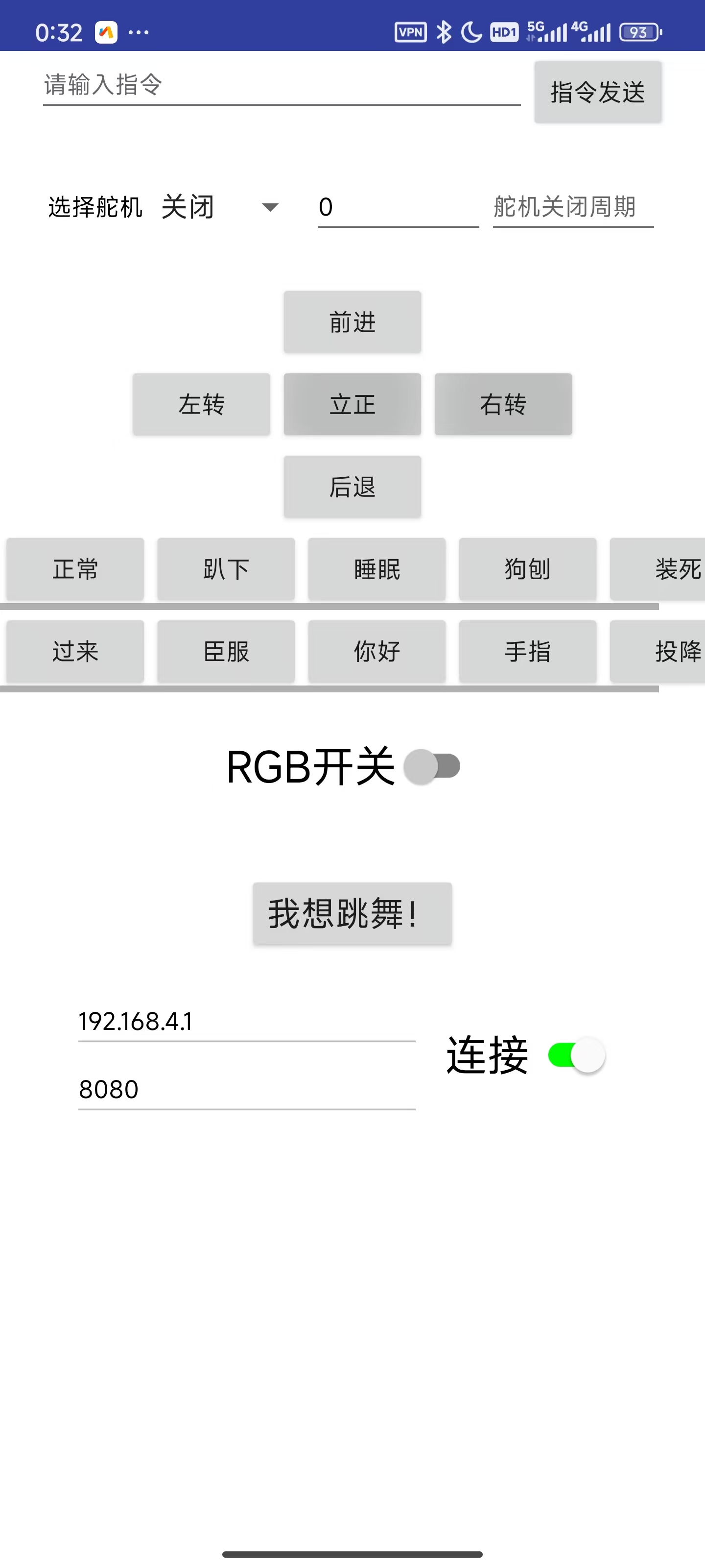
Main controls:
//Command sending section, including the command input box and send button
//Single servo control section, also using the above command sending button.
//5 movement actions: four-way movement and attention, 10 display actions
//RGB switch
//I want to dance! Action 16
//UDP required remote IP and remote port input boxes (automatically entered, or manually) and connection switch
//UDP is not a one-to-one connection like TCP, so the main function of this connection button is to switch panel content
//UDP listening switch and listening display box, which are program-controlled
//AP mode and STA mode buttons, corresponding to AP mode and STA mode on the microcontroller
//Network configuration: WiFi name and WiFi password input boxes, click the network configuration button
//OTA URL input box and send box, used to update the OTA URL.
My GitHub repository
notes:
short-term project, the content is rather rough, there may be strange bugs, no beautification, and the functions are not very complete.
The first download requires a physical connection to the serial port for platformIO download or direct download of the bin file. After that, it can be downloaded over the air via OTA after connecting to the network without the physical serial port.
To use the OTA function, you need to flash the OTA firmware, and the Flash allocation must have space for OTA (which is provided by default).
The M3 holes on the PCB don't align with the holes on the base plate, so I used cable ties to bundle the PCB and base plate together.
The servos must match the serial numbers in my video; otherwise, you'll have to modify the code.
If you bought the quadruped robot kit I linked, you'll need to buy 6-hole servos; otherwise, they won't fit and you
won't be able to write the gait. I directly used the link from this uploader's video and modified it slightly; the forward and backward movement is basically stationary.
I haven't tested whether the WiFi name can use Chinese characters, but the entire project is UTF-8 encoded, so it should be fine.
Don't ask me if you can't access the App Inventor 2 website or my GitHub repository.
The assembly process
will be included in the video.
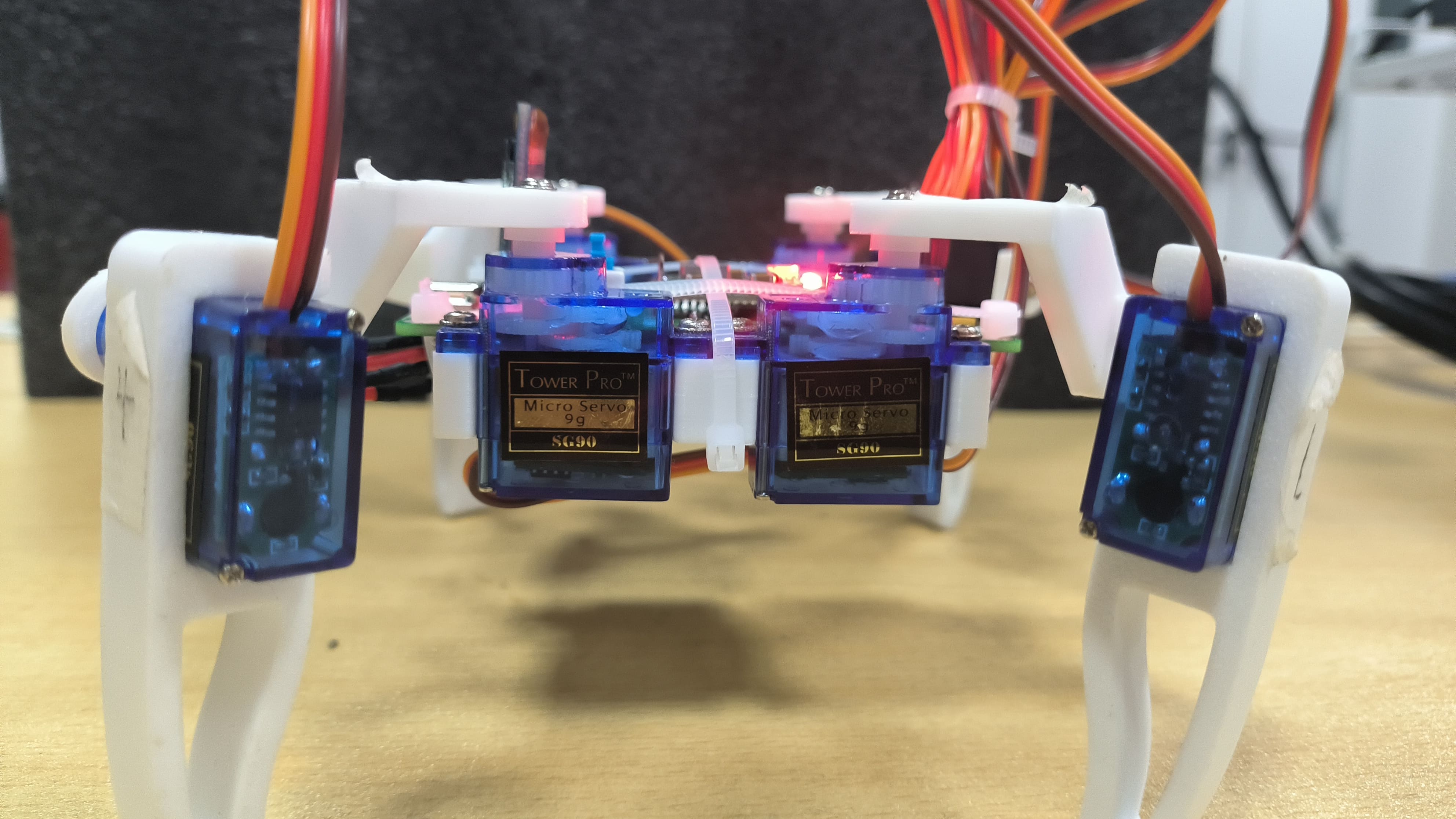
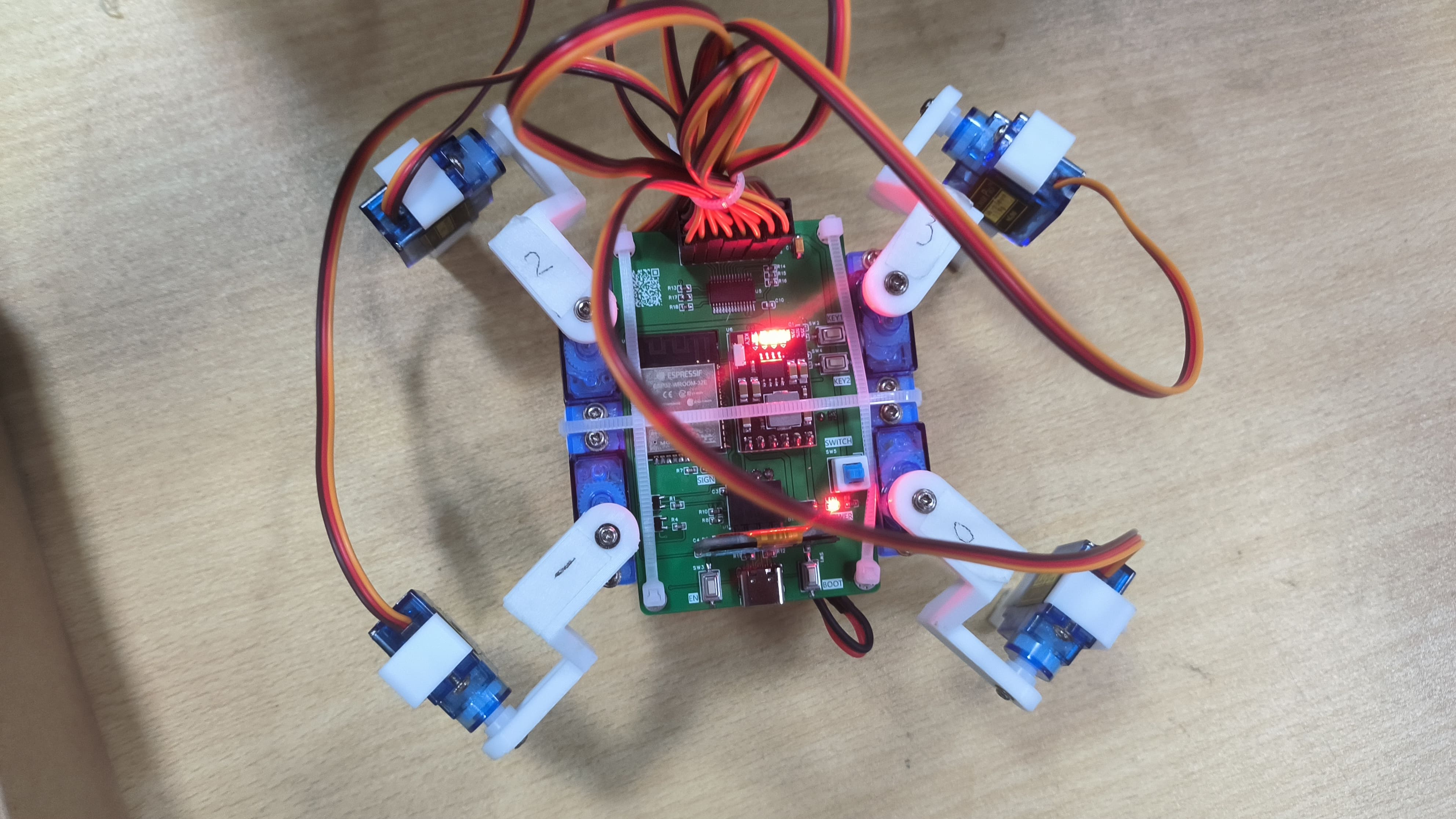
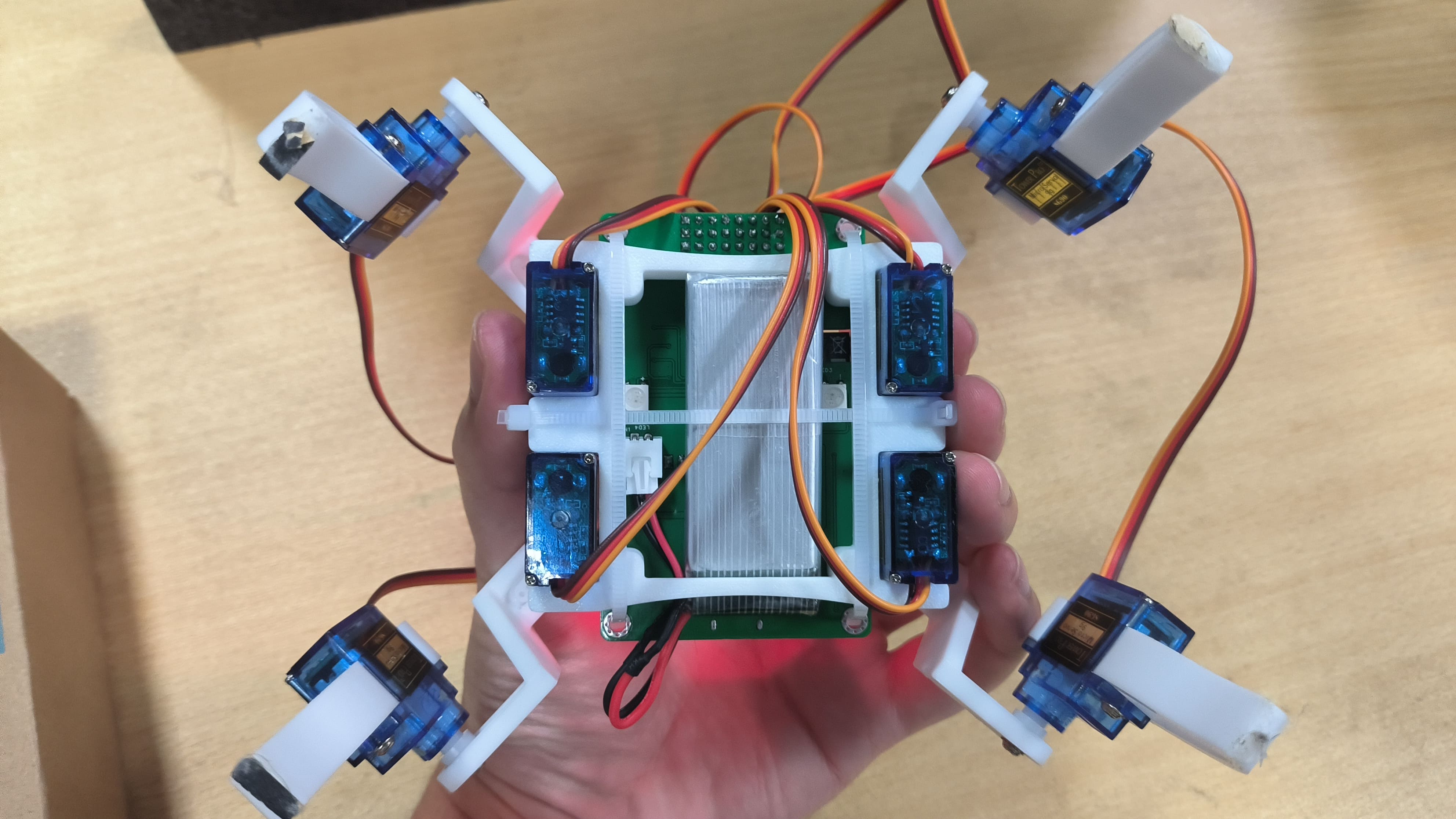
[Images of the actual product:
Front

-
Back
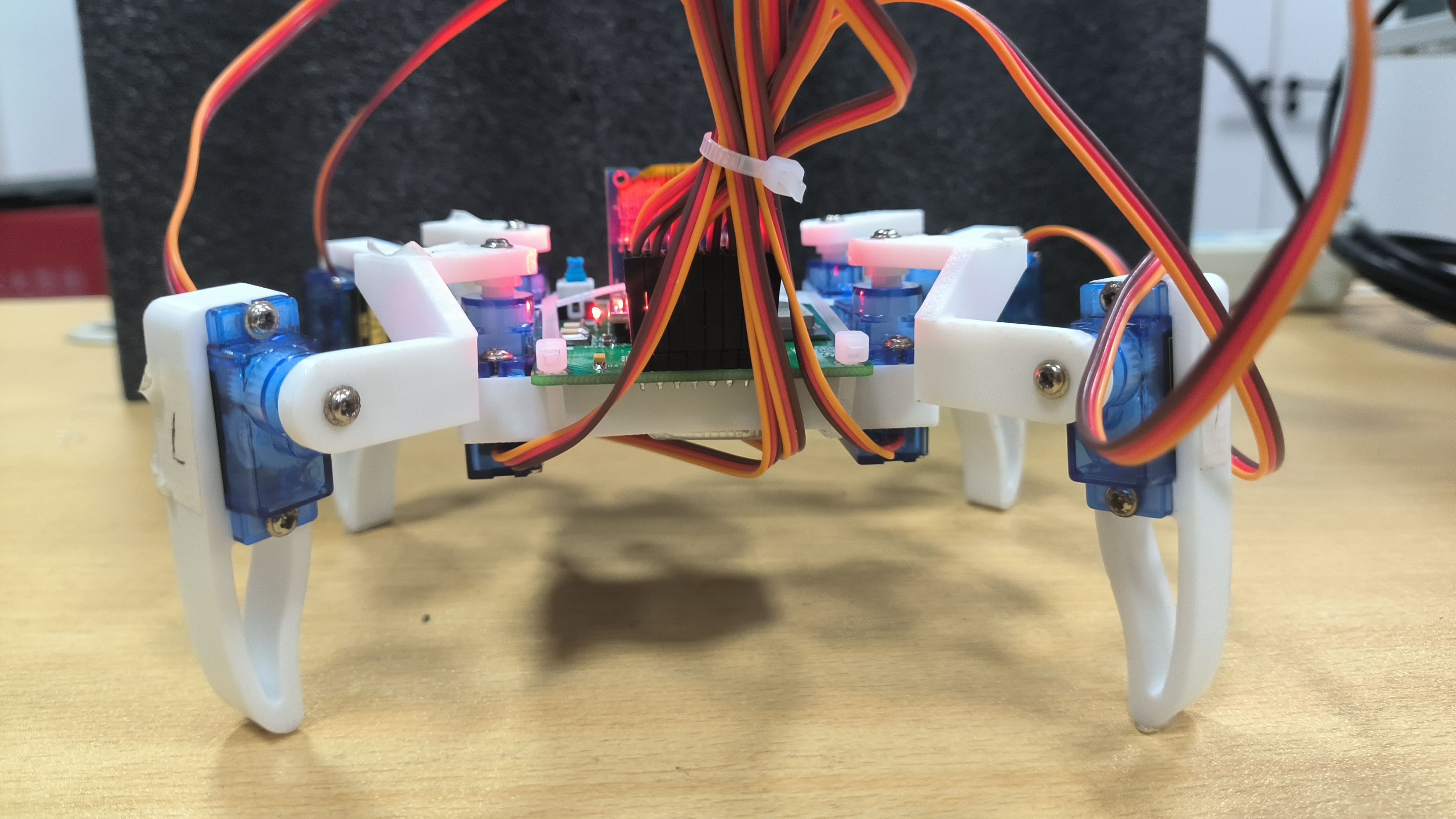
-
Left

-
Right
-
Top
-
Bottom ,
AP Mode,
STA Mode,

Main Control Interface] Finished looking at the main control interface
? Click here to return to the top.


 京公网安备 11010802033920号

 82N26-AB3-G-B


