Debugging in engineering projects
usually requires connecting to a serial port PC, which is cumbersome and could damage the device. Therefore, this portable serial port debugging assistant was developed, featuring an LCD display. Data is directly printed on the LCD screen; you input and send data directly from the screen! It's fantastic!

The device has the following functions:
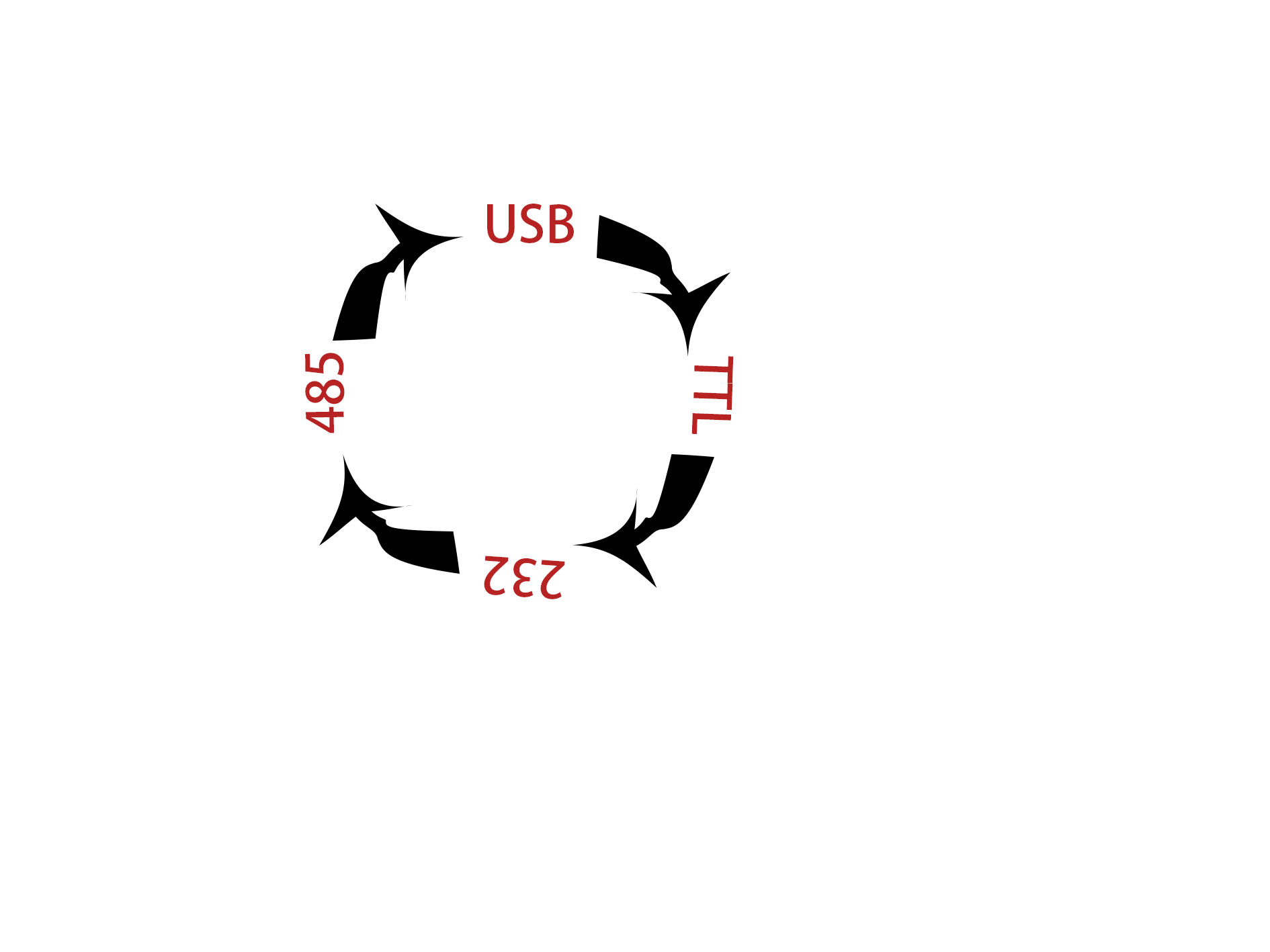
USB to TTL serial to RS485 to RS232,
TTL to serial USB to RS485 to RS232,
RS485 to TTL serial to USB to RS232,
RS232 to USB to TTL serial to RS485, and
USB to TTL serial to RS485 to RS232. All these conversions are possible. The converted data is printed on the LCD screen, and the printed data is translated into TXT and HEX formats. The screen can send TXT and hexadecimal data to USB, TTL serial, RS485, and RS232
communication ports. The baud rate is adjustable, and
data can be sent in a loop.
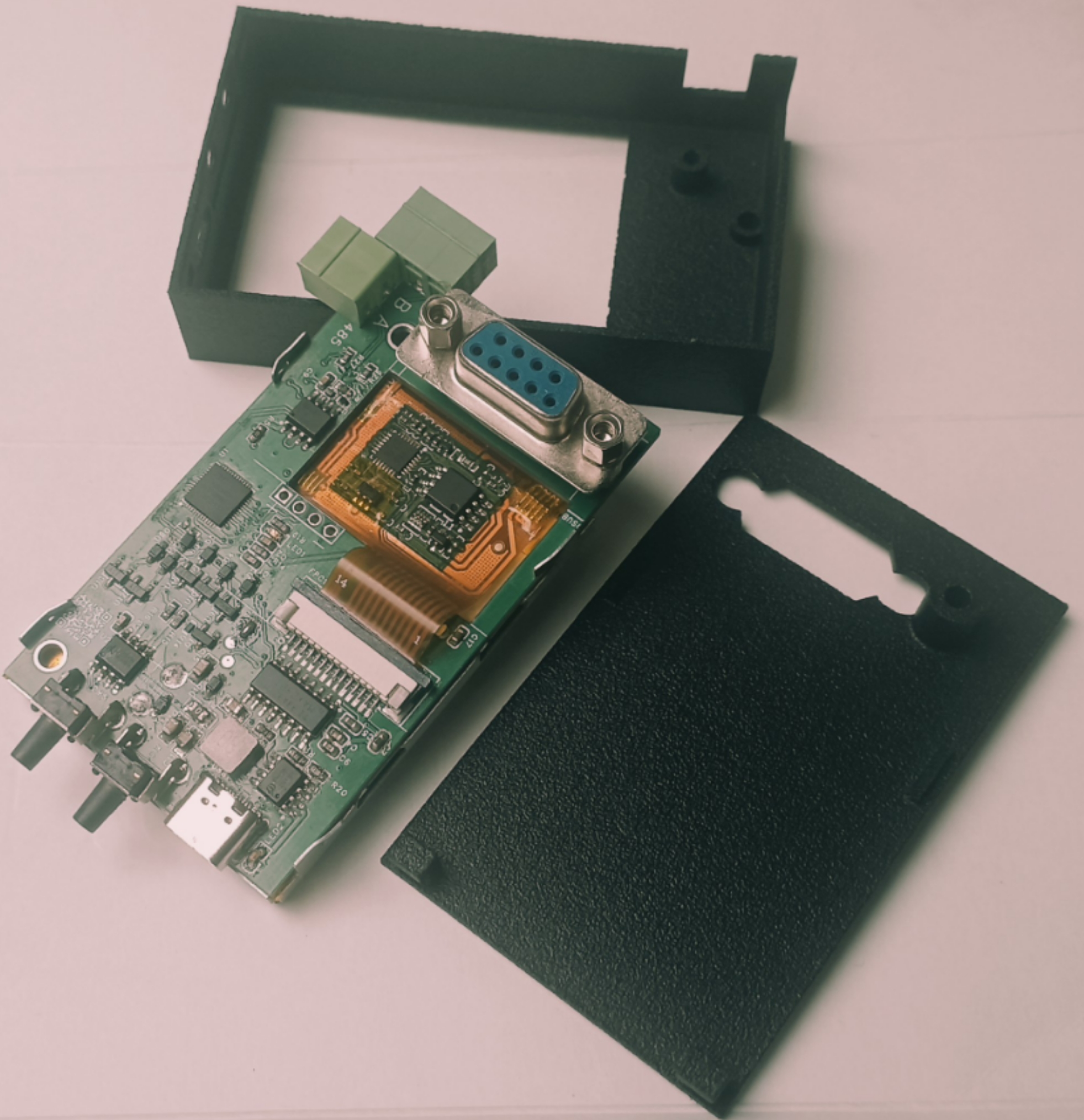
Output interfaces include: USB-Type-C port, TTL serial port, RS485 interface, and DB9P. The RS232 port
integrates charging management, with a typical charging current of up to 1.8A.
It also includes charging indication and power-on/off circuits, eliminating the need to carry a bulky computer for debugging!

Applications:
Used for debugging or communication with industrial equipment, medical equipment, smart devices, and developed products
such as
TTL adjustable data acquisition units, low-power Bluetooth modules, industrial controllers, smart home devices, smart security devices, wireless modules, smart lights, network cameras, smart speakers, etc.
RS485 serial communication is used to control remote devices. It can connect to various devices, including sensors, actuators, PLCs (Programmable Logic Controllers), terminal devices...
Main circuit introduction:
This project uses two buses, one for receiving and one for transmitting, in half-duplex mode.
When one device transmits, only that device cannot receive.
Data transmission and reception of each device are obtained from the bus (except for the 485 transmitter).
The data bus adds a TVS diode for
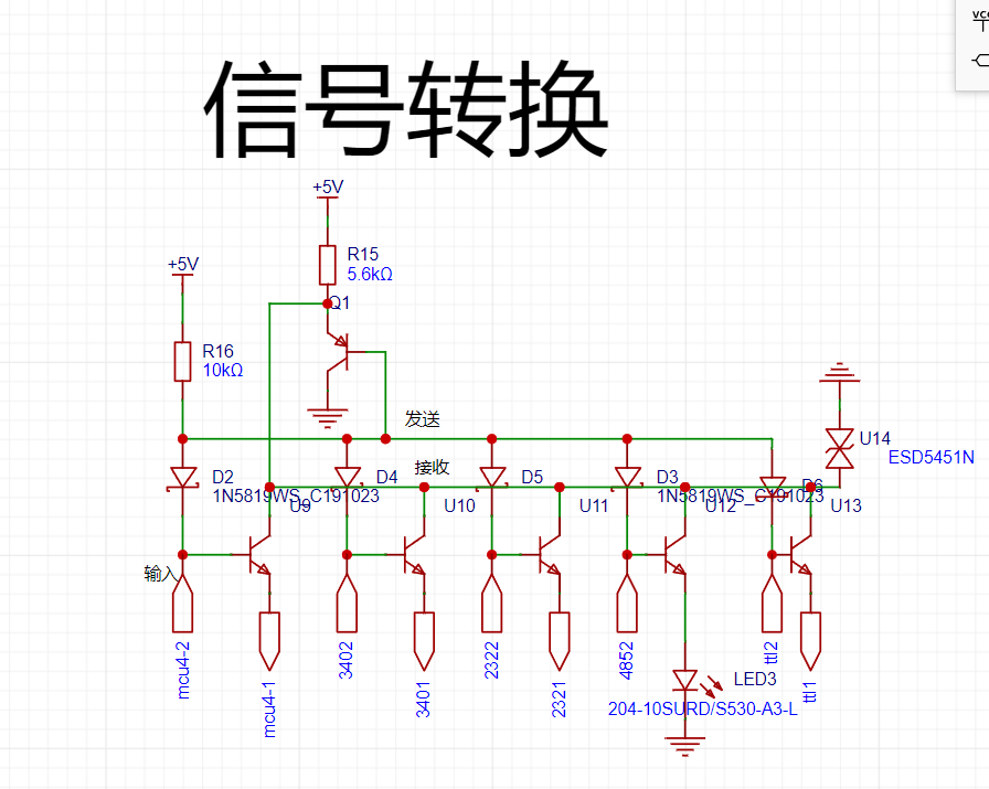
lithium battery charging and discharging management.
Single click: power on. Double click: power off
.
The indicator light flashes when charging . The indicator
light flashes continuously when the battery is almost empty . When fully
charged, the indicator light stays on when powered on


. Program flowchart:
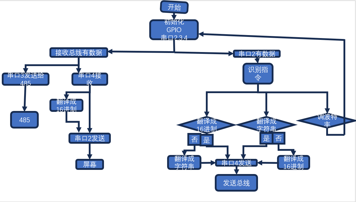
Data to hexadecimal

string to
hexadecimal string to

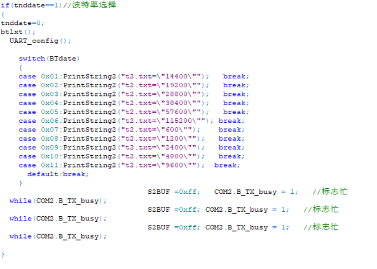
baud rate selection


screen. Program flowchart:

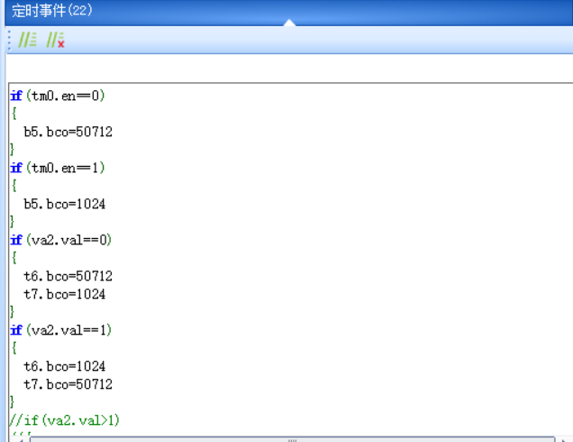
Timer state machine scanning
function interface diagram.
Interface human-computer interaction function:

screen. Purchase link:
Taobao https://m.tb.cn/h.gUKqqpm?tk=Q6SaWBN9v9M HU7632 "Taojingchi USART HMI" The "T1 Series 2.4-inch LCD Screen with 2.4-inch Touchscreen" smart serial port
screen
has a pre-written program; simply download it.
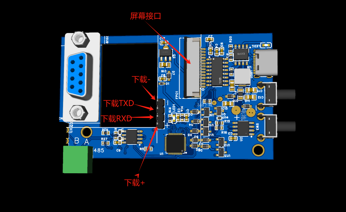
Use a USB-to-TTL programmer to download the program. Connect the power supply, and connect the programmer's TXD to the screen's RxD and RXD to the screen's TXD.
Programmer purchase link:
[Taobao] https://m.tb.cn/h.gUqgoPO?tk=7FcEWBn1beo MF3543 "[Youxin Electronics] 5th Generation STC Full Series Microcontroller Automatic Programmer - Cold Start Download USB to TTL"
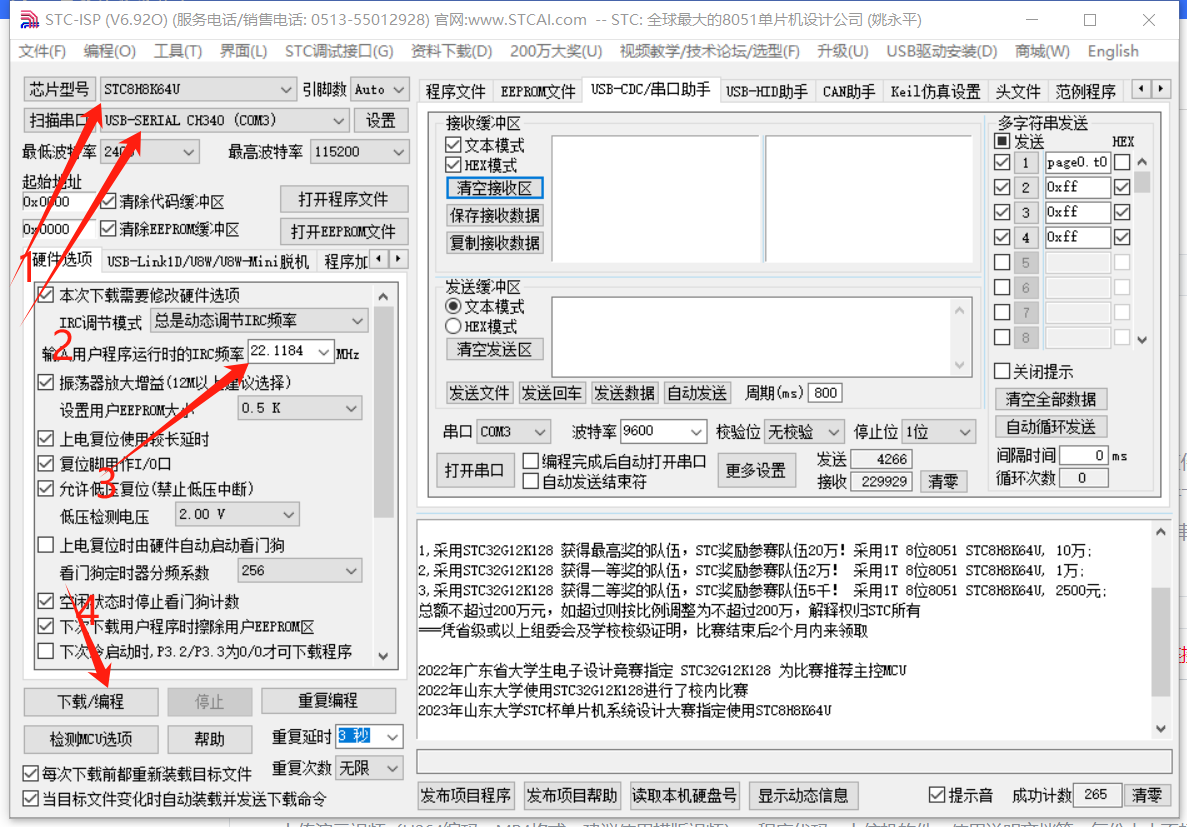
Step 1: Select the correct port number. You need to correctly install the serial port driver. (Refer to Serial Port Driver Installation)
Step 2: Select the download baud rate.
Step 3: Select the TFT file for the screen.
Step 4: Click the Dwon button to download.
Step 5: Remove the screen and assemble it on the serial port device
host. Download:
Use the screen downloader to download.
Do not solder the battery during download, do not plug in the USB port, only power the downloader.
Project Schedule
: 5.20 Initial conception 5.23 Winning the bid 5.24 Determining the implementation method and component selection 5.28 Drawing the schematic diagram 6.05 Placing the PCB order and starting program writing 6.06 Receiving the PCB and testing the circuit function 6.07 Debugging circuit bugs 6.08 Placing the PCB order 6.09 Completing and testing the key algorithm 6.10 Receiving the PCB board 6.11 Completing the manual soldering of the PCB 6.12 Testing the circuit function 6.13 Software and hardware integration testing 6.16 Writing the screen program 6.17 Performing comprehensive testing of the screen program and optimizing the circuit 6.18 Placing the PCB order and starting to draw the outer shell 6.19 Drawing the outer shell, prototyping, assembly, and testing 6.20 Optimizing the outer shell and placing the CNC order 6.21 Modifying the outer shell to 3D prototyping and optimizing the outer shell 7.02 Assembling the outer shell


 京公网安备 11010802033920号

 AZ986-1A-6DC1R1


