The ESP32-C210 wireless soldering iron is a portable, wireless, temperature-controlled soldering iron powered by a built-in lithium battery. It uses a C210 heating element with a maximum heating power of 12W. It supports TYPE-C charging and programming, and can measure and display parameters such as soldering iron temperature, current, voltage, and power.
Features include:
1. Support for constant temperature heating adjustment and calibration from 0℃ to 450℃
; 2. TYPE-C interface for charging the lithium battery and programming
; 3. Three commonly used buttons for mode switching, parameter setting, and one-button power on/off
; 4. A 0.96-inch 160*80 pixel color display showing various parameters
; 5. Maximum 12W heating power and a maximum charging current of 2.1A, supporting simultaneous charging and use;
6. Automatic over-temperature protection, automatic power-off when idle for energy saving, LED auxiliary lighting, and a buzzer.
Project attributes:
1. This project is being publicly released for the first time and has not won any awards in other competitions. It is an original CC BY-SA 4.0 open-source project created by the author, "Negative Entropy Life Light".
2. This project is licensed under the "CC BY-SA 4.0" license. Please include the original source link and this statement when reprinting. For commercial use, please obtain authorization from the original author.
4. Gitee Repository: https://gitee.com/arduino2021/projects?sort=&scope=&state=public
5. Negative Entropy Light 2024-7-7
Project Progress
: 1. April 2024: Schematic and PCB design of the ESP32-C210 wireless soldering iron, and prototyping for functional verification.
2. May 2024: ESP32-C210 wireless soldering iron shell 1.0 structural design, and 3D prototyping for functional verification at LCSC.
4. June 2024: ESP32-C210 wireless soldering iron shell 2.0 structural design, and 3D prototyping for functional verification at LCSC.
5. This project iterated through two versions of the shell, including PCB prototyping, shell 3D prototyping, and purchasing related components.
Design Principles
: 1. This project uses the ESP32-C3FH4 as the main controller, using an ADC to collect the soldering iron thermocouple temperature signal to control the PMOS switch to control the soldering iron temperature and heating power
. 2. The IP5306 chip is used to charge and boost the voltage of the lithium battery to 5V to power the C210 soldering iron.
3. The GS8331-TR is a precision amplifier that amplifies the thermocouple temperature signal of the C210 soldering iron core by constructing a non-inverting amplifier circuit
. 4. The XB7608AJ provides overvoltage, undervoltage, overcurrent, and short-circuit protection for the lithium battery cells . 5.
The LIS3DHTR is used for motion detection to determine whether to enter the power-saving shutdown mode.
6. The TP181A1-CR is used to collect the current supplying the C210 soldering iron core for heating power control.
Function mode buttons
: 1. Constant temperature heating mode: Short press K1 to switch between standby and working modes; long press K1 to enter the power-saving shutdown mode; short press K2 and K3 to set the target temperature; long
press K2 and K3 to switch between different modes. 2. Function setting mode: Short press K1 to switch between different function settings; long press K1 to enter and exit the more detailed parameter setting interface; short press K2 and K3 to turn functions on or off, and increase or decrease parameters
. Calibration Setting Mode: Short press K1 to switch between different calibration parameters; long press K1 to enter and exit the more detailed parameter setting interface; short press K2 to subtract, add, or turn on/off parameters.
4. Power-Off Saving Mode: In power-off saving mode, short press K1 to enter the constant temperature heating mode interface. In the constant temperature heating mode interface, long press K1 to enter the power-off saving mode.
1.
Switch between standby and working modes by short pressing K1; short press K2 and K3 to set the target temperature; long press K2 and K3 to switch between different modes.
2. In standby mode, only the soldering iron temperature is measured without heating.
3. In working mode, the soldering iron temperature is measured and heated to the set target temperature.
4. Target temperature range: -99℃~450℃.
5. Soldering iron temperature measurement range: 0℃~450℃. The range and accuracy are affected by temperature calibration parameters.
6. When no movement is detected, the power-off saving countdown begins; the countdown restarts when movement is detected.
7. When the lithium battery voltage is detected to be below 3.1V, it will enter power-saving mode. When the temperature is detected to be above 65℃, it will enter standby mode.
Function settings:
1. Short press K1 to switch between different function settings. Long press K1 to enter and exit the more detailed parameter setting interface. Short press K2 and K3 to turn functions on or off, and increase or decrease parameters
. 2. Maximum current setting: Set the maximum heating current to prevent excessive current from draining the battery voltage and causing low voltage protection.
3. Working mode setting: Default standard heating mode. Intelligent heating mode will automatically increase the temperature by 50℃ when large solder joints are detected. (Currently not perfect)
4. Motion detection setting: Set the acceleration detection threshold to provide the current status for the sleep countdown.
5. Sleep time setting: Set a power-saving countdown of 1 to 60 minutes. If the device is stationary and the set time is exceeded, it will enter power-saving mode.
6. Screen orientation setting: Set the screen orientation by short pressing K2 and K3.
7. Auxiliary lighting setting: Set the LED auxiliary lighting switch.
8. Buzzer switch setting: Set whether the buzzer sound is on or off.
9. Restore default settings: Setting parameter 1 restores all parameters to their default values and saves
the calibration settings. Mode
1: Short press K1 to switch between different calibration parameters. Long press K1 to enter and exit the more detailed parameter setting interface. Short press K2 to subtract, increase, or turn parameters on or off
. Mode 2: Measure the actual temperature of the soldering iron using an external, precise thermometer to adjust the set temperature value. Maintain the soldering iron at the desired calibration temperature, then press the calibration switch to save the corresponding soldering iron thermocouple voltage. Mode
3: When calibrating the voltage, the default calibration starts from 0℃. Place the soldering iron tip in an ice-water mixture for a while before calibration, then calibrate step by step. 500℃ may exceed the range. Mode
4: Temperature calibration is best done with a professional thermometer. If calibration is not possible, a small deviation is acceptable. Mode
5: The default calibration parameters are obtained using a multimeter and are not very accurate. Thermocouple voltages of soldering irons from different manufacturers are likely to differ; calibration is required before use.
Mode 6: The default measurement range is 0℃ ~ 450℃. However, because the C210 soldering iron's thermocouple temperature signal is too small between 0~50℃, the temperature measurement deviation is too large. (
Software instructions)
1. This program is developed based on the Arduino IDE. The source code, dependent libraries, and pre-compiled programming files are included in the attachment. This project provides two programming methods. Beginners are advised to use the official ESP tool.
2. To program via the official ESP tool, you need to install esp32 flash_download_tool_3.9.5, load the programming bin file, configure the corresponding parameters, download, and restart.
3. To program via the Arduino IDE, you need to install the esp32 development board and related libraries, and select the corresponding chip parameters. Installation package version: esp32_package_2.0.14
4. Before programming the chip, you need to solder the lithium battery and ensure the relevant hardware is properly soldered. Then, compile and configure the programming software correctly to ensure normal programming and operation. The relevant configuration parameters are included in the attachment.
5. When programming the chip for the first time, first insert the TYPE-C interface, press the K3 button, then press and hold the K1 button to power on. Then release the K3 button to enter the forced download mode and click the computer programming button.
6. After successful programming in forced download mode, release the K1 button and then press and hold the K1 button again to power on. If the computer indicates that the burning process failed, focus on checking the hardware soldering and burning configuration for any issues.
7. If after successful burning there is no response, the screen is black, or there are abnormal display phenomena, it is recommended to focus on checking the hardware soldering, screen model, and whether the download parameter configuration is correct .
Hardware Assembly
1. The EESP32-C210 wireless soldering iron consists of: PCBA + lithium battery + 0.96 TFT + two shells + C210 soldering iron core.
2. The PCB is prototyped using JLCPCB. Process parameters selected: FR-4 material, 2-layer board, board thickness 0.8mm, color optional.
3. The lithium battery uses 102050 cells with a capacity of 1000mAh, length 50*width 20*height 10mm. It is best to use a high-performance battery cell to provide sufficient heating power; ordinary battery cells are barely usable.
4. The shell is designed using SOLIDWORKS 2021 and 3D printed by JLCPCB. It consists of shell A and shell B. Since the connection between the two shells is not very tight, it is best to reinforce the connection with glue or tape.
5. The TFT uses ST7735S 0.96-inch TFT. 160*80 pixels, plug-in 8-pin FPC interface. Note: ST7735S driver required
. 6. The C210 soldering iron uses the Sugon C210-018 tip soldering iron core. Measured heating resistance: approximately 2R. Thermocouple signal: approximately 0~5mV at 0~500℃. Precautions
:
1. This project uses a large number of 0402 packaged components, making hand soldering difficult. It is recommended to use JLCPCB SMT. This project is highly complex; proceed with caution.
2. Lithium battery cell electrodes can be soldered to the PCB with thick wires. Ensure correct positive and negative terminals; do not solder backwards. Use cells without protection boards to reduce internal resistance.
3. For 3D printing the shell, choose high-temperature resistant materials whenever possible. A high-precision UV-curing printer is recommended for printing high-temperature resistant resin materials.
4. Some parameters may be abnormal upon initial use. Try restoring to default settings. After entering power-saving mode, the IP5306 standby current is approximately 40uA.
5. This soldering iron is suitable for portable, low-power soldering scenarios. The maximum 12W heating power is insufficient for high-temperature, large-pad soldering.
6. Due to size limitations, this soldering iron can only theoretically last 17 minutes with a 1Ah lithium battery and a maximum heating power of 12W. Under normal use, it lasts for over 30 minutes and supports simultaneous charging and use. 7. When using
a regular lithium battery with low voltage, it will not provide sufficient heating power and may easily trigger the low-voltage protection of the lithium battery, causing it to shut down. It is recommended to use a high-performance lithium battery.
8. Component parameters are based on the schematic diagram. Components not available on the LCSC website can be found on Taobao. Related hardware and software materials are included in the attachments. The schematic diagram contains relevant notes.
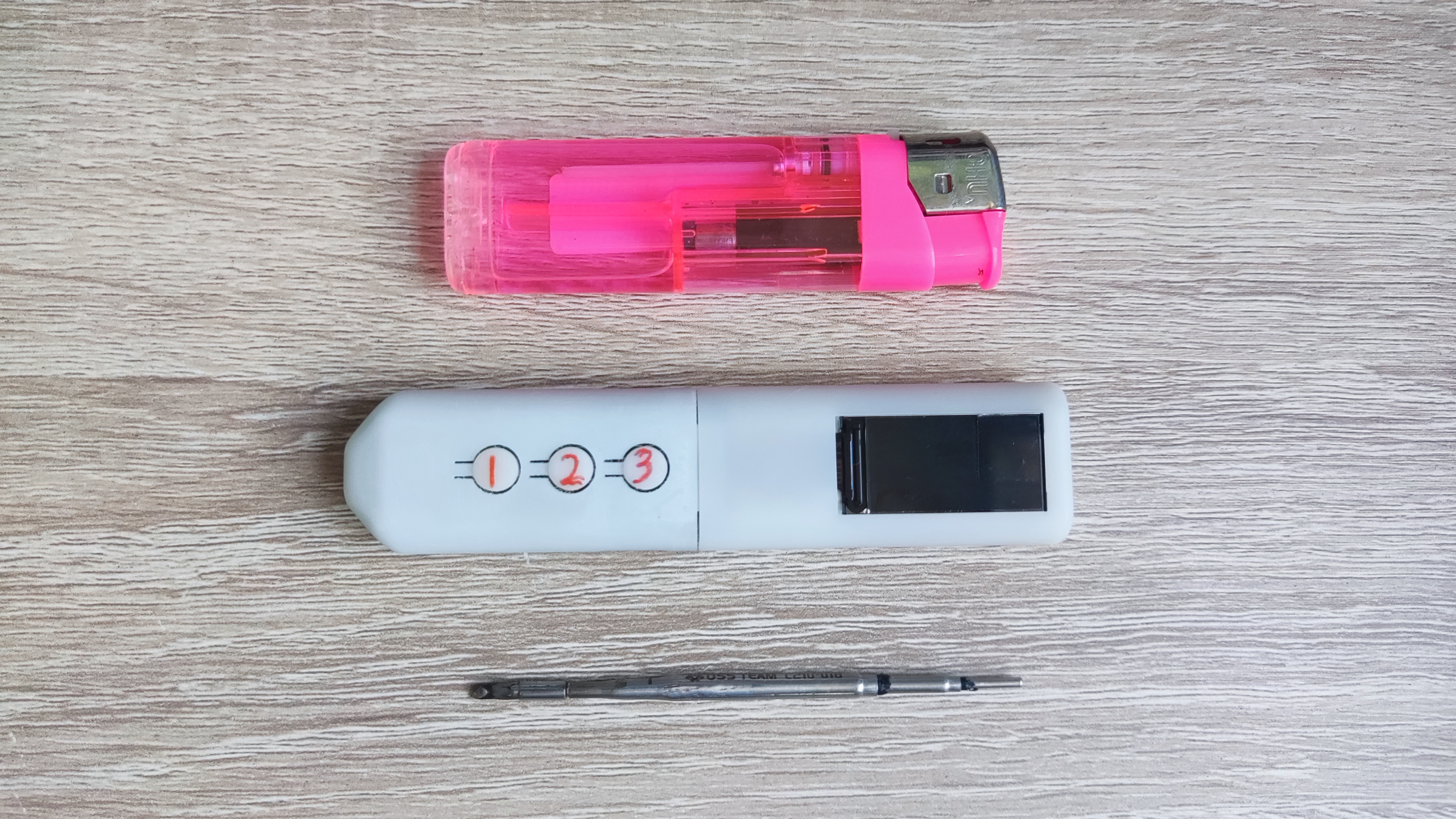
9. This project is a personal DIY project and has not undergone professional evaluation and testing. There may be hidden bugs. Reproduce and use with caution; assume all risks. (
Actual product shown)


 京公网安备 11010802033920号

 1KS206-176TT


