Abstract: Gallium
nitride (GaN) is a novel power device material with advantages such as high speed, high efficiency, and high reliability. Therefore, it has attracted much attention in the field of switching power supplies, and the application of GaN devices in switching power supplies is constantly expanding, involving many different application areas. This paper introduces a synchronous rectified negative voltage driven GaN digital power supply using an STM32F334C8T6 microcontroller as the controller, an NCP51820 as the half-bridge driver, and an IGT60R070D1 as the GaN power device. This module can perform boost and buck operations on the input voltage, and the output voltage is adjustable. Buck and boost topologies and various control modes are implemented through microcontroller control.
Keywords: synchronous rectification; gallium nitride HEMT; BUCK-BOOST; negative voltage drive; STM32; digital power
Gallium Nitride Buck-Boost Switching Power Supply based on STM32
Abstract: Gallium nitride (GaN) is a new type of power device material, with high speed, high efficiency and high reliability and other advantages, so in the field of switching power supply attention, GaN devices in the field of switching power supply applications are expanding, has been involved in many different applications fields. This paper introduces a kind of digital power supply with STM32F334C8T6 single chip microcomputer as controller, NCP51820 as half-bridge driver, IGT60R070D1 as gallium nitride power device. The module can boost and reduce the input voltage, and the output voltage can be adjusted. buck, boost topology and various control modes are realized by MCU control.
Keywords: Synchronous rectification; Gallium nitride hemt; Negative voltage drive; Digital power supply
1 Introduction
Gallium nitride (GaN) is a novel power device material with advantages such as high speed, high efficiency, and high reliability. Therefore, it has attracted much attention in the field of switching power supplies, and the application of GaN devices in switching power supplies is constantly expanding, involving many different application areas. Utilizing the knowledge learned in university, this study designed a GaN Buck-Boost power supply based on STM32. Through this design, we can improve our ability to comprehensively apply knowledge of electronic technology, gain a deeper understanding of electronic technologies such as microcontrollers and switching power supplies, cultivate our practical work ability, and improve our self-learning ability, laying a necessary theoretical and practical foundation for future work in related fields.
2. Introduction to Bidirectional BUCK-BOOST Topology
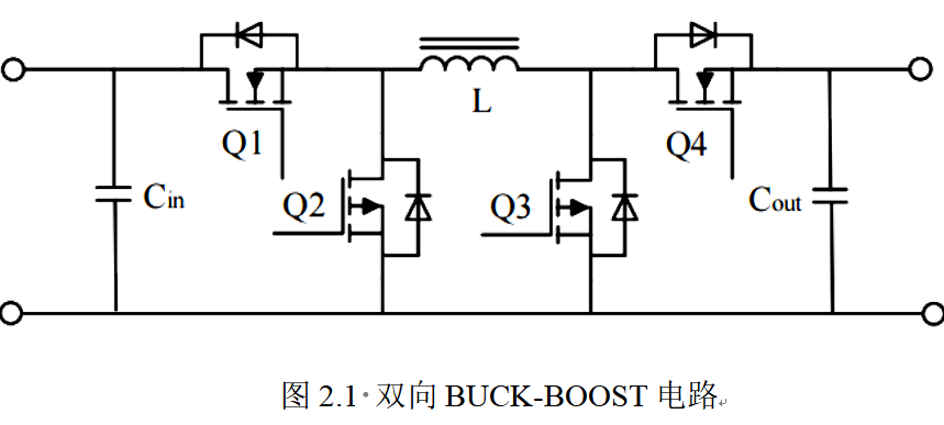
Combining the BOOST equivalent circuit with the synchronous BUCK circuit constitutes the bidirectional BUCK-BOOST circuit. Conventional BUCK and BOOST diodes are used for freewheeling, but due to their forward voltage drop, they are prone to large conduction losses under low voltage and high current conditions. In contrast, GaNE-HEMT devices have very low on-state resistance when turned on, and their voltage drop is significantly lower than that of diodes. Replacing BUCK and BOOST freewheeling diodes with GaNE-HEMT devices can effectively reduce the conduction losses of the devices. This method is called "synchronous rectification".
This project proposes to use synchronous BUCK and synchronous BOOST circuits. A synchronous BUCK step-down circuit will be formed using GaNE-HEMT transistors Q1 and Q2 and inductor L. A synchronous BOOST step-up circuit will be formed using GaNE-HEMT transistors Q3 and Q4 and inductor L. The synchronous rectification BUCK-BOOST structure is symmetrical, meaning that GaNE-HEMT transistors Q3 and Q4 and inductor L can form a synchronous BUCK step-down converter circuit, and together with GaNE-HEMT transistors Q1 and Q2 and inductor L, they can form a synchronous BOOST step-up converter circuit. This allows for simultaneous voltage boost/drop in both directions, meaning the energy in the circuit can flow bidirectionally.
The working principle of the circuit is analyzed below. When Q4 is on and Q3 is off, Q1 and Q2 conduct alternately with a certain duty cycle, the circuit is in operation, as shown in Figure 2.2. When Q1 is on and Q2 is off, Q3 and Q4 conduct alternately with a certain duty cycle, the circuit operates in BOOST mode as shown in Figure 2.3. When Q1, Q2, Q3, and Q4 are alternately connected with a specific duty cycle, the circuit operates in BUCK-BOOST mode, i.e., mixed mode (MIX mode), as shown in Figure 2.1.
2.1 BUCK Operating Mode
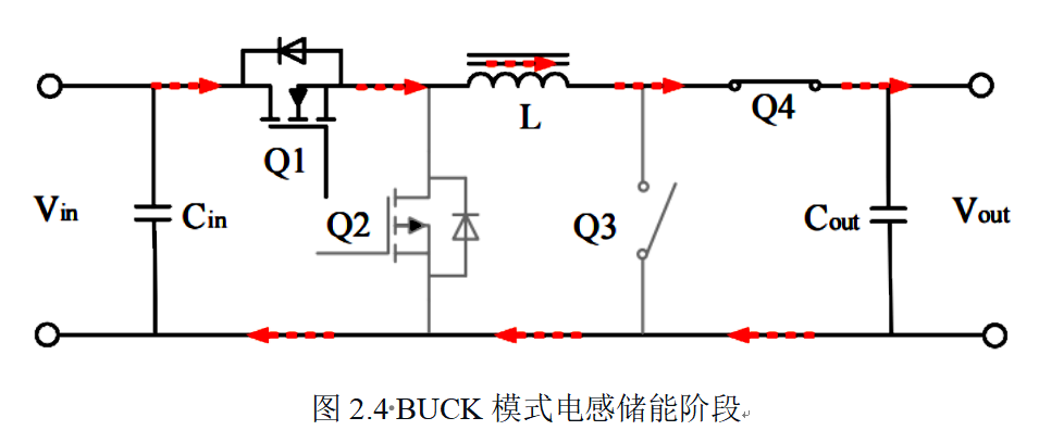
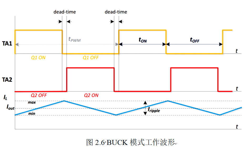
: When the output voltage is lower than 80% of its input voltage, the circuit operates in the chopper-buckling region, i.e., BUCK mode. In this mode, Q1 and Q2 conduct alternately with a certain duty cycle, Q3 remains off, and Q4 remains on. The circuit topology is equivalent to the synchronous rectification BUCK circuit topology. In this design, Q1 and Q4 serve as the upper transistors of the two half-bridges in the circuit. A bootstrap boost drive circuit composed of a bootstrap diode and a bootstrap capacitor is used. This means that for Q4, Q3 needs a specific and relatively fixed on-time within each PWM switching cycle; otherwise, when the energy stored in the bootstrap capacitor of Q4 is depleted, causing a voltage drop, Q4 will be turned off because the gate drive voltage is below the conduction threshold. In other words, this design allows Q3 to conduct with a very small duty cycle, while Q4 conducts with a large duty cycle approaching 100%. With Q1 on and Q2 off, the equivalent topology of this circuit is shown in Figure 2.4. Here, the input voltage Vin is stored in the inductor L through Q1, and the load is charged. The voltage across the coil is Vin minus Vout, so the current in the inductor rises linearly. Both the inductor and the output capacitor are storing energy.

When Q1 is disconnected and Q2 is connected, the equivalent circuit topology is shown in Figure 2.5. Because the current in the inductor cannot change suddenly, the induced current will not change either, and it continues to flow through Q2. Therefore, the voltage across the inductor is negative Vout, and the current flowing through the inductor also decreases linearly. The inductor releases energy at this time.
The waveforms of Q1 and Q2 drive and inductor current are shown in Figure 2.6.
2.2 BOOST Operating Mode
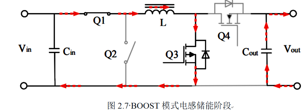
When the output voltage is significantly higher than the input voltage (VIN is less than 80%), the circuit enters BOOST mode. At this time, Q3 and Q4 switch according to a specific duty cycle. Q1 remains on and Q2 remains off, which is equivalent to BOOST.
However, with Q3 on and Q4 off, its equivalent circuit is shown in Figure 2.7. Here, the input voltage Vin stores and charges the inductor L through Q3, resulting in a voltage equal to Vin across the inductor. The current flowing through the inductor also increases linearly. At this time, the inductor stores electrical energy and temporarily provides power to the load through the output capacitor, thus maintaining the output voltage.
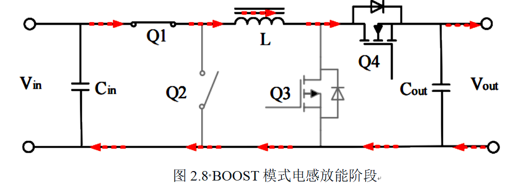
When Q3 is off and Q4 is on, its equivalent topology is shown in Figure 2.8. The voltage applied to the inductor is Vin minus Vout, and the current flowing through the inductor decreases linearly. The inductor releases the energy, and the energy in the inductor does not replenish the energy output by the output capacitor in the previous stage.
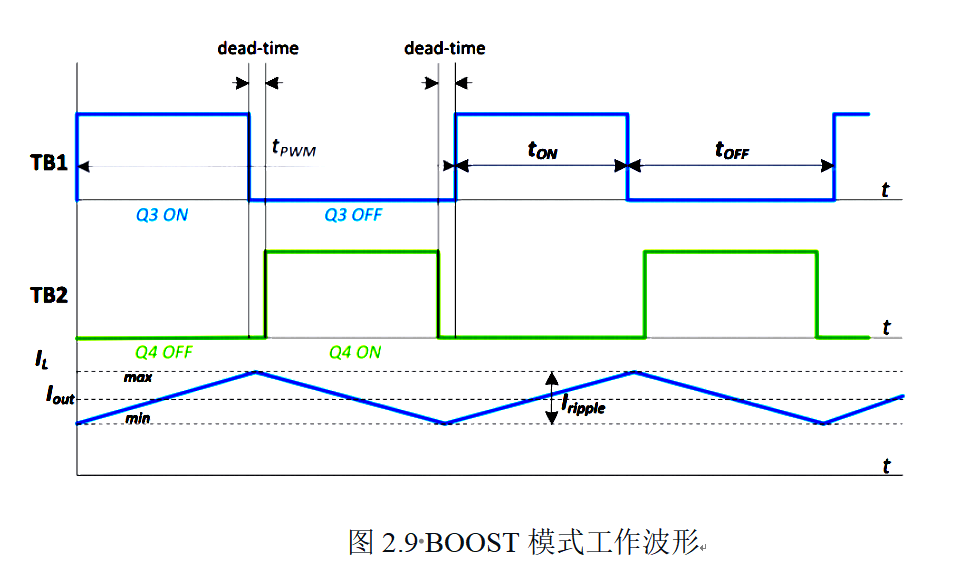
The inductor current waveform and the drive waveforms of Q3 and Q4 are shown in Figure 2.9.
2.3 BUCK-BOOST Mode (MIX Mode)
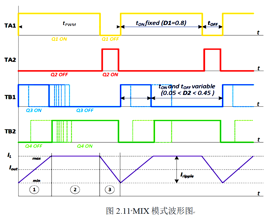
When the input and output voltages are the same, neither the BUCK nor BOOST mode can adequately meet the high-precision operating requirements. At this point, both BUCK and BOOST operating modes need to work simultaneously. Within a single PWM switching cycle, Q1 and Q2 conduct alternately with specific and fixed duty cycles, as do Q3 and Q4.
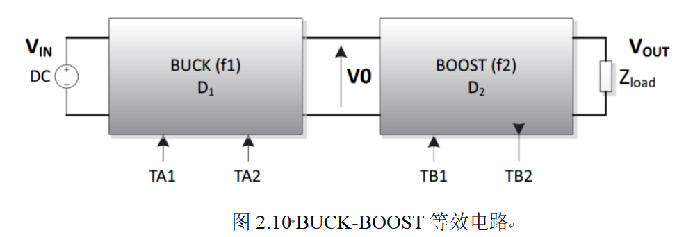
Let the PWM duty cycle of the BUCK chopper circuit be D1, the PWM duty cycle of the BOOST boost circuit be D2, and the output voltage of the BUCK chopper be V0, which is also the input voltage of the BOOST boost circuit. The equivalent structure of this circuit can be seen in Figure 2.10.
When the circuit operates in MIX mode, both the PWM duty cycle D1 of the BUCK circuit and the PWM duty cycle D2 of the BOOST circuit have a combined effect on the output voltage.
Since the output voltage of the circuit in BUCK-BOOST mode is close to the input voltage, the duty cycle of the BUCK mode can be set to a fixed 80%. Adjusting the PWM duty cycle of the BOOST circuit in this mode allows for flexible adjustment of the output voltage. Based on the two operating modes analyzed earlier, Figure 2.11 shows the waveforms of the inductor current and the PWM duty cycle under BUCK and BOOST operating modes.
Combining the above three operating modes, the input and output voltage amplitudes pass through the sampling circuit and signal conditioning circuit to the microcontroller. When the measured operating voltage is below 80%, the MCU controls the operation in BUCK mode; when the measured operating voltage is above 120% of the input voltage, the microcontroller will operate in BOOST mode; when the input voltage changes within the range of 80-120%, the MCU will operate in MIX mode.

3. Introduction to Gallium Nitride HEMT
3.1 Principle and Characteristics of GaN Enhancement High Electron Mobility Transistor (E-HEMT)
In AlGaN/GaN heterojunctions, a lateral two-dimensional electron gas (2DEG) is formed through a special material structure. This 2DEG has extremely high charge density and electron mobility, which are key factors in improving device performance. In the manufacturing process of gallium nitride (GaN) devices, in order to ensure that the device can be in a stable cut-off state when there is no gate voltage and to achieve the so-called normally off characteristic, the gate is usually P-type doped, such as using magnesium as the doping element. This doping method can effectively deplete the two-dimensional electron gas in the heterojunction, thereby forming a normally off device. It is worth noting that this type of gallium nitride switching device not only has excellent switching performance, but also its working principle is similar to that of metal oxide semiconductor field-effect transistor (MOSFET), showing excellent electronic device characteristics.
3.2 Similarities between HEMT and conventional silicon MOS
1. Like MOS, it belongs to the true enhancement-mode device (normally closed device).
2. After being turned on, it can only remain on when the gate leakage current IGSS is supplied.
3. The switching rate can be controlled according to the change of RG.
4. Compatible with most silicon MOSFET driver chips.
3.3 Differences between HEMT and conventional silicon MOS
1. Extremely low QG: lower drive loss; faster switching speed [8].
2. Higher transconductance and lower VGS: Only a +5V to 6V gate bias voltage is required to turn on the device.
3. Lower VG(th): Typical value is 1.5V.
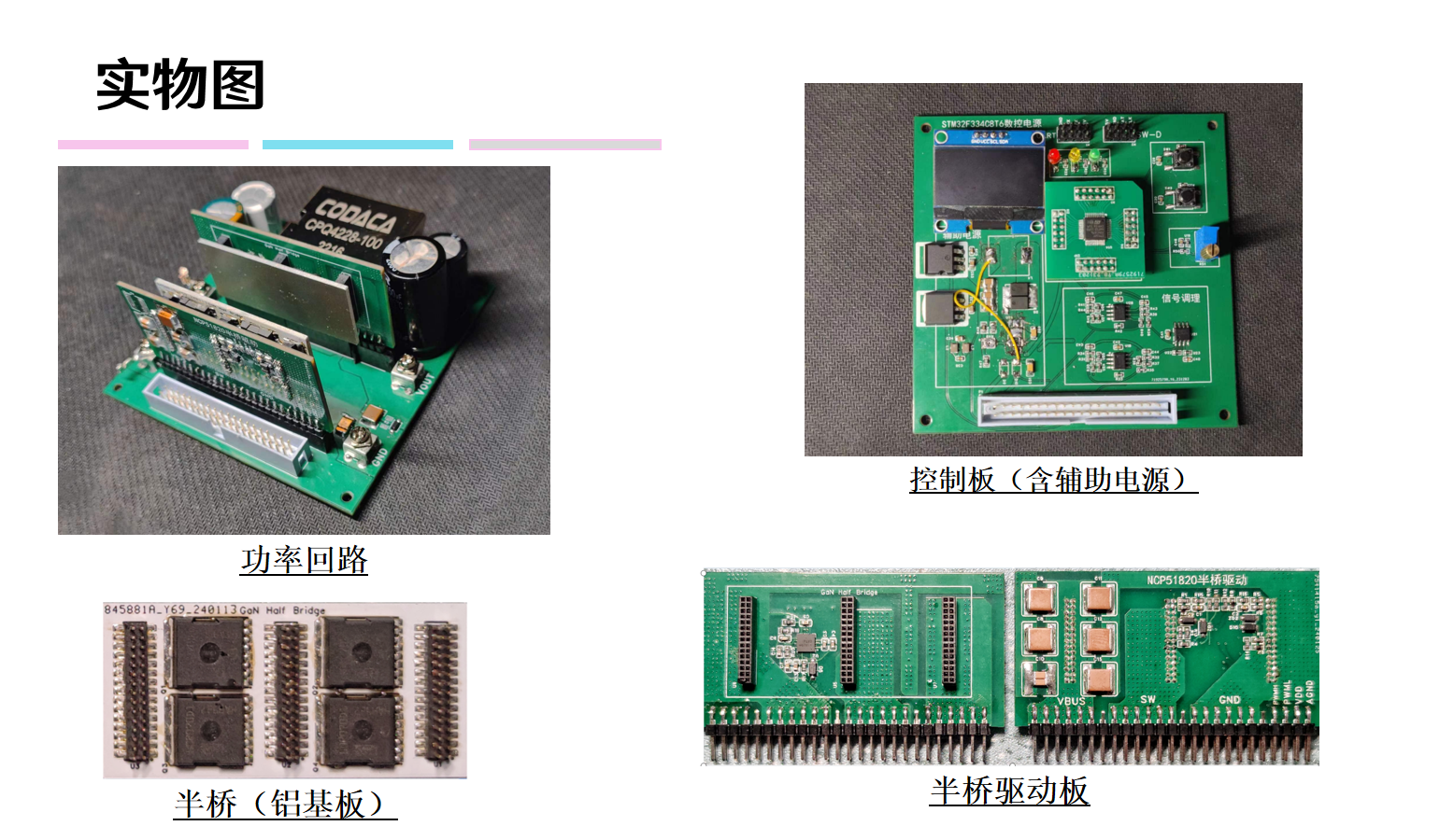
The bidirectional synchronous automatic buck-boost power supply in this design mainly consists of two gallium nitride half-bridges, each with a high-order GaN E-HEMT transistor. Traditional drive circuits seen in other papers generally use isolation drivers or pulse transformers to drive the high-order GaN E-HEMT transistors, but this leads to circuit complexity, increases design complexity and prototype size, and using gate isolation transformers may cause efficiency degradation due to potential drive losses.
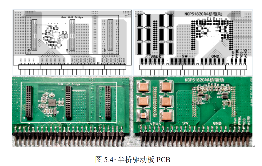
This design uses two NCP51820 high-speed gate drivers to drive the two half-bridges respectively. It is specifically designed to meet the stringent requirements of drive enhancement mode (E-mode) high electron mobility transistors (HEMTs) and gate injection transistors (GITs), as well as gallium nitride (GaN) power switches in offline, half-bridge power topologies. This driver features a short, matched propagation delay and employs advanced level-shifting technology, providing a common-mode voltage range of -3.5V to +650V (typical) for the high-side driver and ±3.5V for the low-side driver. Furthermore, the device offers stable dV/dt operation, achieving a 200V/ns rating for both driver output levels in high-speed switching applications. To fully protect the gate of the gallium nitride power transistor from excessive voltage stress, dedicated voltage regulators are used in both drive stages to accurately maintain the amplitude of the gate-source drive signal. This circuit actively regulates the driver bias voltage and prevents potential gate-source overvoltage under various operating conditions. The NCP51820 also provides important protection features such as independent undervoltage lockout (UVLO), monitoring of VDD bias voltage and VDDH and VDDL driver biases, and thermal shutdown based on device junction temperature. Programmable dead-time control is configurable to prevent cross-conduction, increasing system reliability.
The microcontroller requires a 3.3V operating voltage, the half-bridge driver requires a 12V operating voltage, and the operational amplifier requires a 5V operating voltage. The maximum input voltage is 100V, therefore an auxiliary power supply is needed. This paper selects the MP9486A, which employs hysteresis voltage control mode for rapid response to load changes. Because the chip's switching frequency is as high as 1MHz, small-sized inductors and capacitors can be used. Over-temperature protection and short-circuit protection (SCP) ensure stable and reliable operation of the power supply. A 170µA quiescent current helps improve light-load efficiency.
The main controller of the digitally controlled bidirectional synchronous BUCK-BOOST converter uses the STM32F334. Output voltage or current signals are acquired via an ADC, and combined with output voltage or current reference signals generated by a sliding potentiometer, output voltage closed-loop control or output current closed-loop control is achieved after calculation by a specific loop compensator.

Figure 6.1 shows the overall program architecture. After power-on reset, the program initializes each functional module. The core program runs via interrupts, not the main.C file.

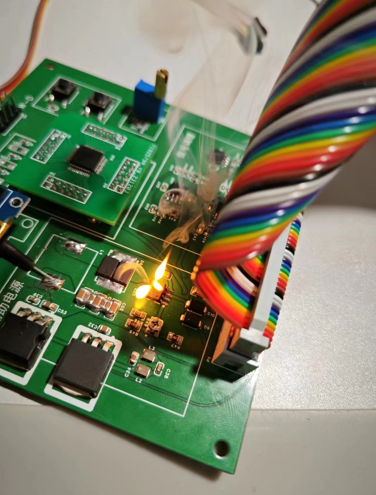
A small board was made specifically for the microcontroller for quick replacement. It has a soft, foolproof corner-cutting mark, but it's not foolproof; brute force won't work.
The auxiliary power supply's output capacitor should be a high-ESR electrolytic capacitor; don't just use a bunch of large-capacity MLCCs. See the datasheet for details.

Be careful when modifying the program; don't force it. The auxiliary power supply can't handle over 300V output.
Buy a used IGT60R070D1 GaN transistor from Taobao; they're very cost-effective.
You can request samples from Keda Jia or replace
the inductor. When making the board, remember to attach the MOSFETs. The half-bridge board is aluminum-based; don't make the mistake of choosing the wrong one like Zheng** from the 2022 class, who gave me a yellowish single-layer FR4.
The code has some strange bugs, the negative voltage drive seems to need fine-tuning, and the 200K switching frequency can't bring out the full performance of gallium nitride. I will gradually optimize it and increase the integration to improve the power density later.


 京公网安备 11010802033920号

 SDNT2012X104K4250HTF


