This project involves a self-made voltmeter and ammeter based on the CW32F030C8T6 microcontroller.
As a beginner, the design references the schematic diagram from a training camp, which can be found here: [link to CW32 Digital Voltmeter and Ammeter Training Camp Project Tutorial Document].
For a more detailed project introduction, please refer to this link: [link to CW32 Digital Voltmeter and Ammeter Expansion Board].
An ADC (Analog-to-Digital Converter) is an indispensable key component in electronic systems. It converts continuous analog signals into digital signals, enabling digital processing and analysis. ADCs play a crucial role in signal conversion, measurement and data acquisition, control system input, and communication and signal processing. Their widespread application promotes the intelligent and precise control of electronic equipment in various industries and is one of the key factors driving modern technological progress.
The CW32 is a microcontroller based on the ARM Cortex-M0 core. It boasts rich peripheral interfaces and excellent performance, making it ideal for developing measurement devices such as voltmeters and ammeters.
System Overview:
The main objective of this project is to design and develop a voltmeter and ammeter based on the CW32 microcontroller. This meter will accurately measure and display voltage and current values. During the design process, special attention was paid to the device's high accuracy and low power consumption to ensure superior performance in practical applications.
Hardware Design:
Microcontroller Unit: The CW32 was chosen as the main control chip for this device, responsible for data acquisition, processing, and display control.
Voltage Measurement Unit: Through a carefully designed voltage divider circuit, the voltage to be measured is reduced to a range acceptable to the CW32 microcontroller's ADC module, and then accurately sampled by the ADC.
Current Measurement Unit: To accurately measure current, a current transformer or shunt resistor is used to convert the current signal into a voltage signal, which is then sampled by the ADC module.
Display Unit: To display the measured voltage and current values in real time, two 3-digit common-cathode LED displays are used. (I used the same color here; after testing, I recommend using different colored LED displays for a more intuitive display.) Power Management Unit:
We designed a stable power supply circuit to ensure a stable and reliable power supply for the CW32 microcontroller and other peripheral circuits.
Software Design:
Initialization Program: This includes configuring the system clock and initializing peripherals (such as ADC, GPIO, LCD, etc.).
Data Acquisition Program: An ADC sampling program was written to periodically read voltage and current signals and perform necessary digital filtering to improve data accuracy.
Data Processing Program: This program is responsible for converting the ADC sampled values into actual voltage and current values, including unit conversion and calibration.
Display Control Program: The processed data will be formatted and output to the display unit for dynamic display.
User Interaction Program: A button function was designed, allowing users to select ranges and perform other operations, improving the ease of use of the device.
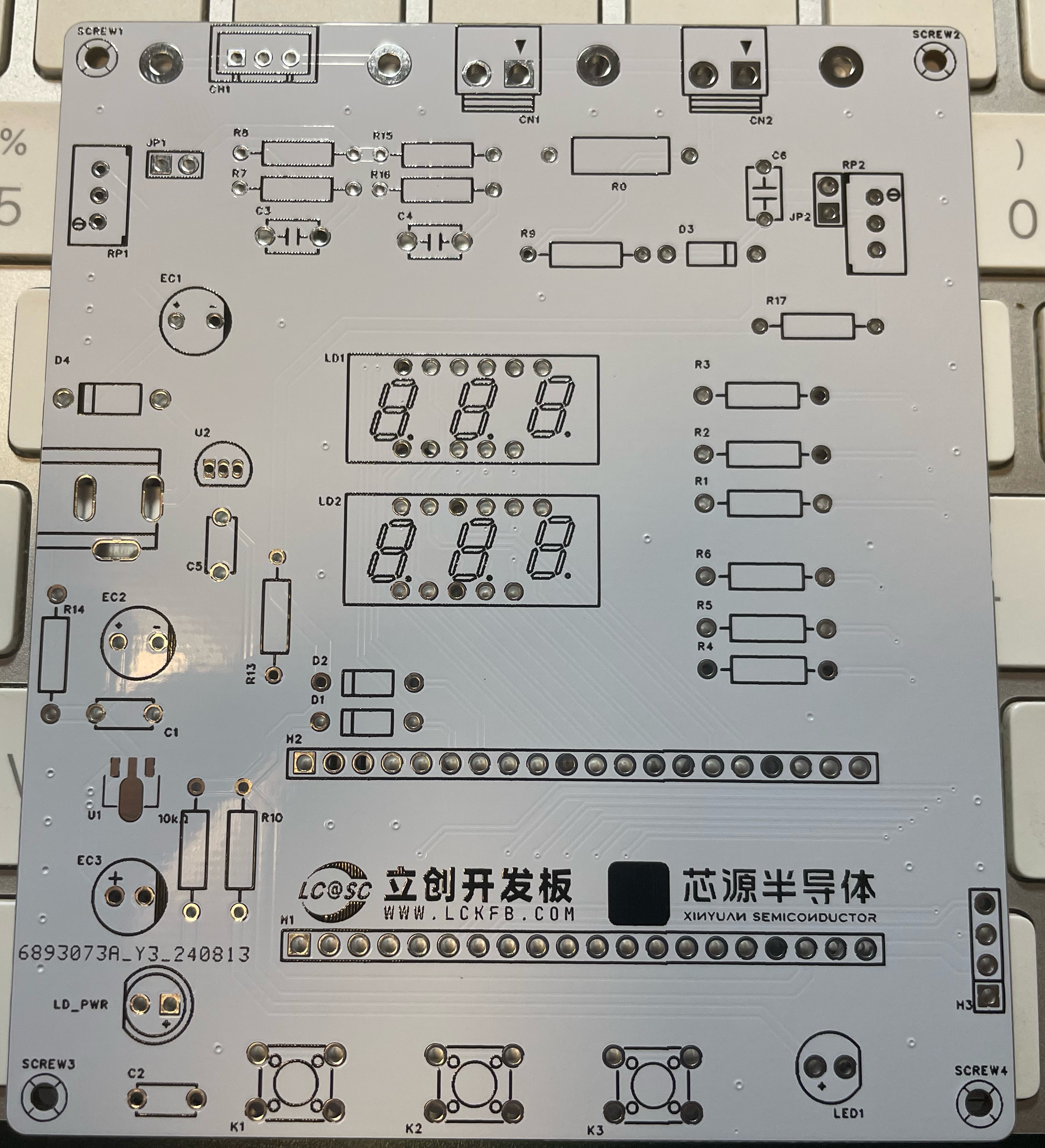
PCB Finished Product 3D Rendering:

The PCB board just unpacked:

Comparison of the actual product and the 3D rendering after soldering:
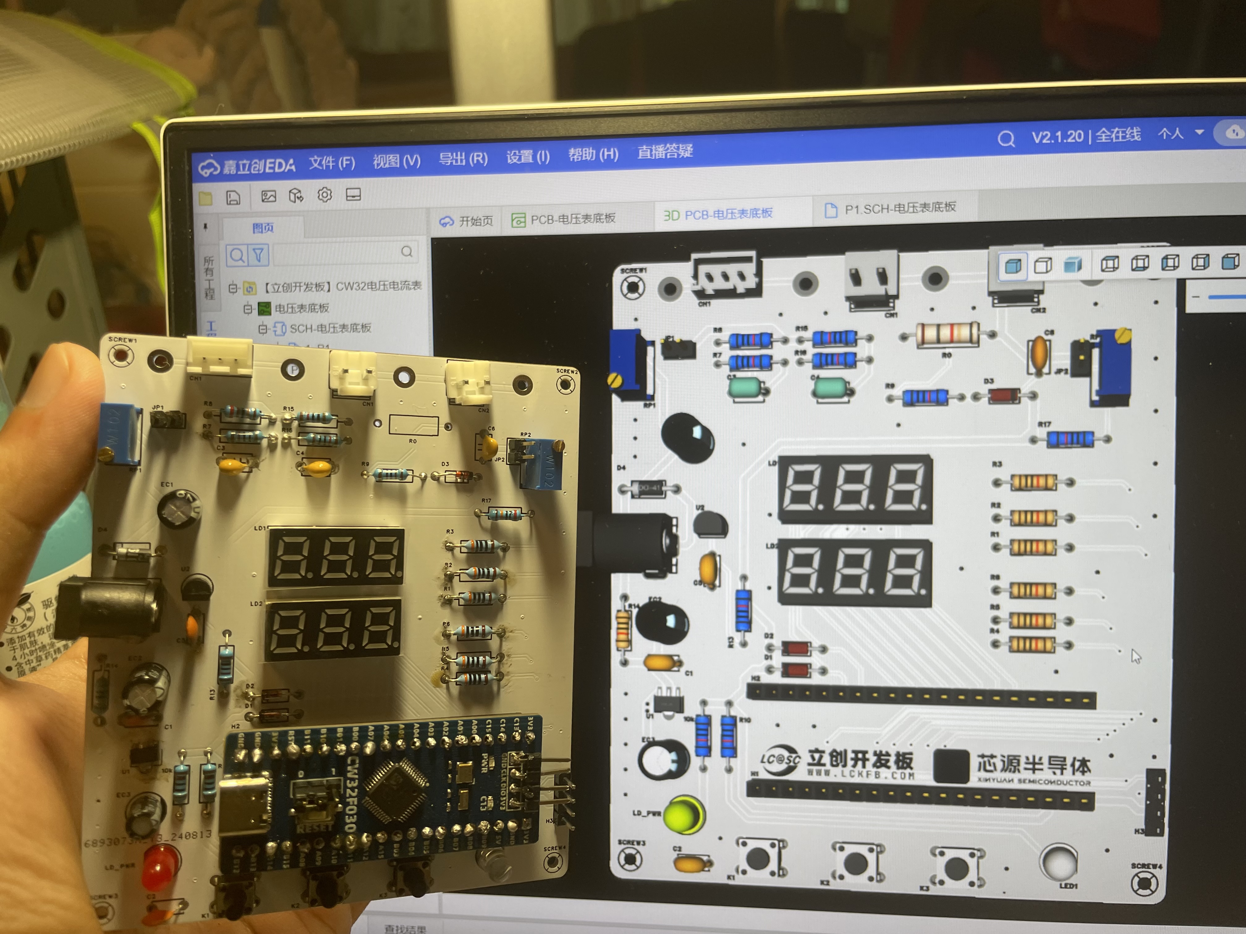
As you can see, since almost all components are through-hole, it is quite user-friendly for a soldering novice like me.
Housing Installation Demonstration:
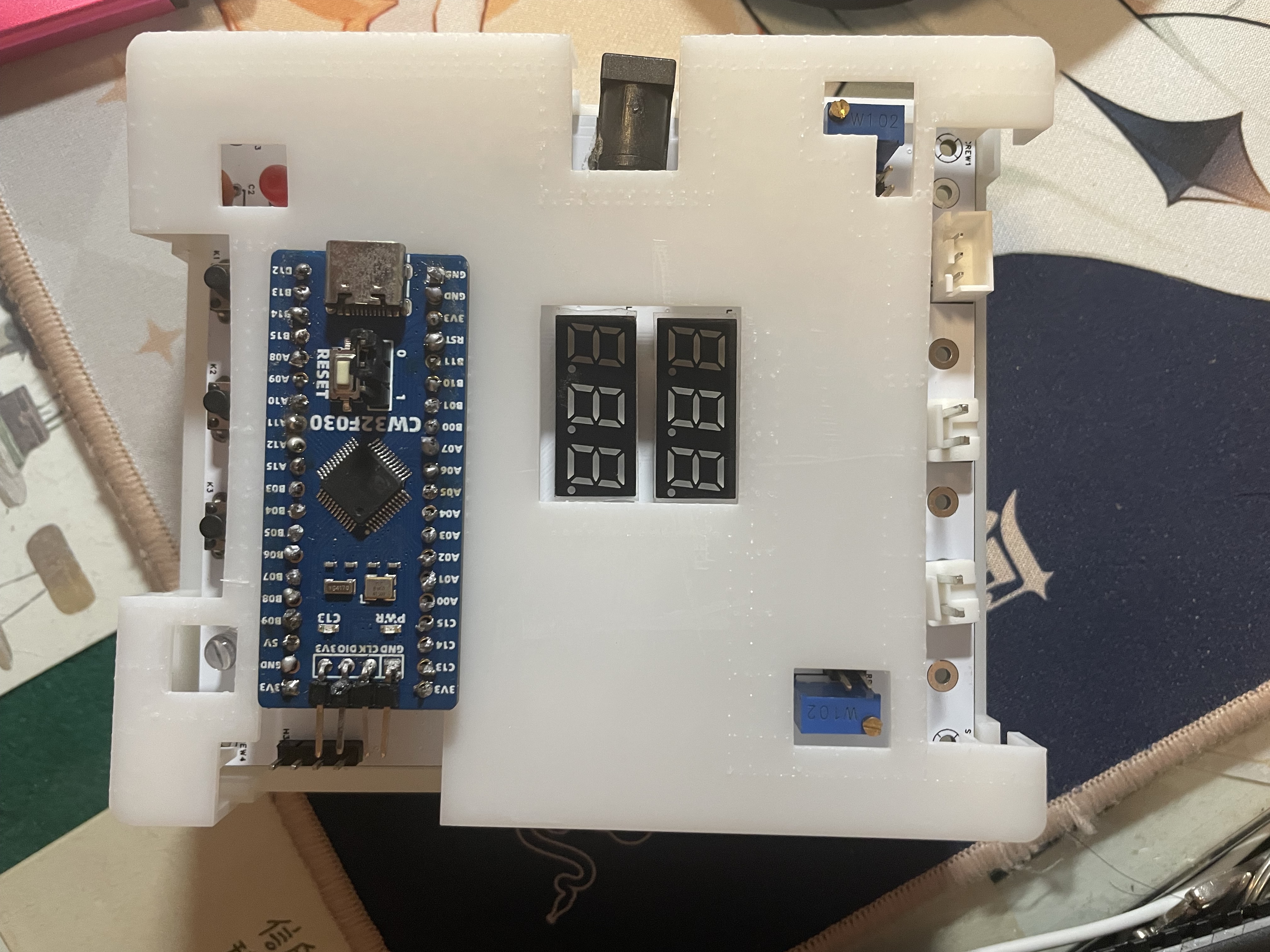
Some issues can be found in the housing design; excessive holes significantly reduce the housing's strength. This must be considered in future housing designs.
Power-On Demonstration:
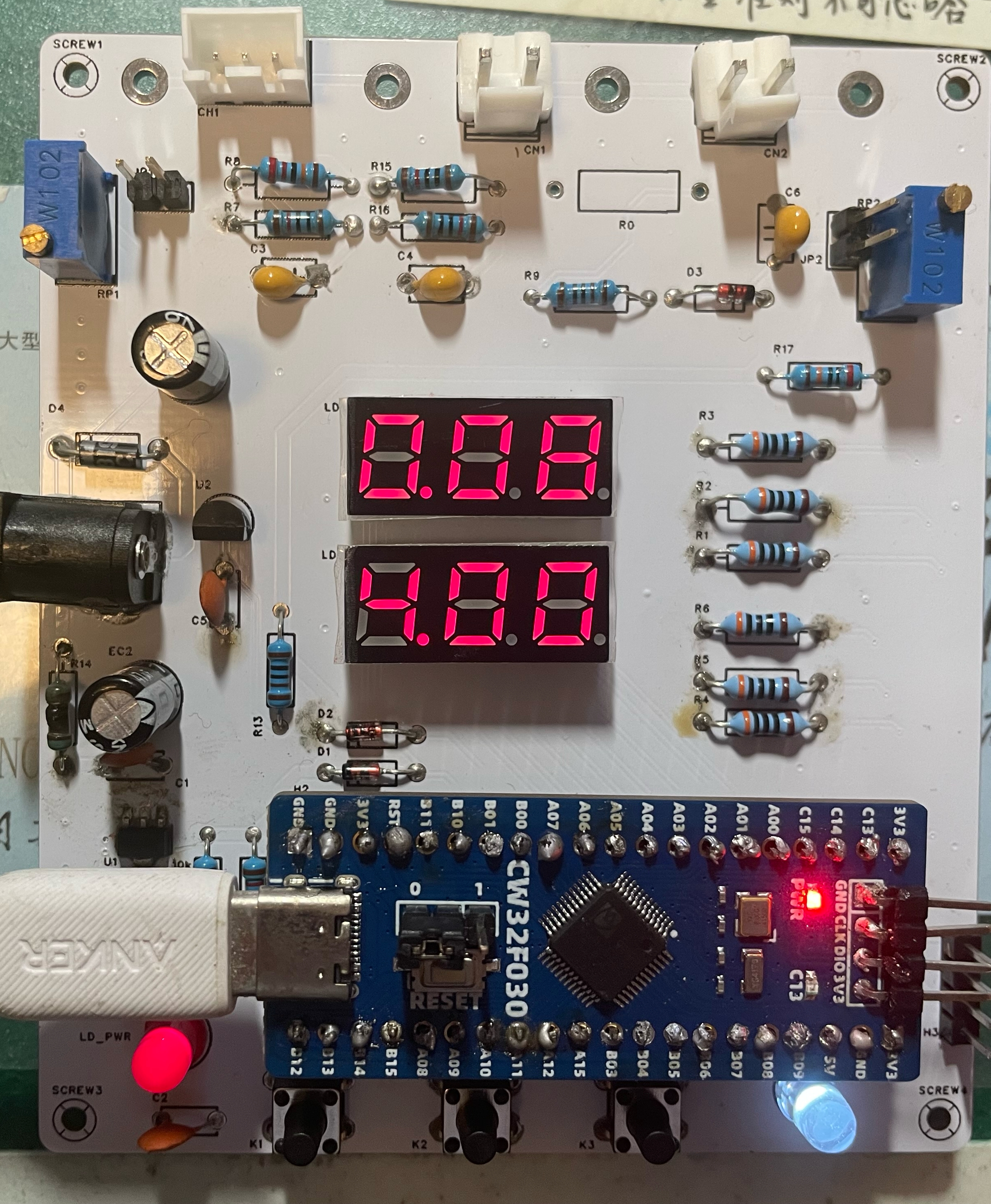
Currently, due to being away from the campus, some necessary debugging equipment is lacking. I will further complete and improve these issues after returning to campus.


 京公网安备 11010802033920号

 NCT04DH161F408TRF


