Originally planned to be completed in three months, the bbAir bubble display, after much experimentation, learning, and relentless effort, was finally finished a year later.
This is my most knowledge-intensive DIY project to date, and while there were many setbacks along the way, I also learned a great deal.
Many technical details and behind-the-scenes stories are not shown in the video due to time constraints.
Regardless, it's a project I'm very satisfied with, especially since experiencing it firsthand makes the sense of accomplishment all the more profound. The video quality has also improved somewhat.
Open source link: https://github.com/RealCorebb/bbAir
Watch videos ▶️:
Bilibili
Youtube

PDF_bbAir Bubble Display.zip
Altium_bbAir Bubble Display.zip
PADS_bbAir Bubble Display.zip
BOM_bbAir Bubble Display.xlsx
91024
ESP32S3 LCOS Mini Projector
This is a small LCOS projector driven by an ESP32S3 chip, with a resolution of 320*240.
This is a small LCOS projector driven by an ESP32S3, with a resolution of 320*240.
I previously open-sourced a small projector using an LCD screen, but the effect wasn't good. A friend recently recommended this stock optical engine, and the effect is much better than the previous LCD screen version.
The LCOS modules for this project were found on Xianyu (a second-hand marketplace), 5 for 50 yuan. Those who want to replicate it should buy the optical engine as soon as possible, as the quantity of this LCOS module on Xianyu seems to be limited. (
Packaging is shameful! Don't package!
Packaging is shameful! Don't package!
Packaging is shameful! Don't package!)
[Xianyu] https://m.tb.cn/h.5PMdZ6i?tk=rIbQWe9RBtp CZ3457 "Come grab a bargain! [Mini projector LED light head, LCOS model, see the last picture, the light source is exceptionally bright]" Click the link to open
Xianyu. The optical engine is gone. This project cannot be replicated
, please do not make any boards.
The LCOS model is Lijing Optoelectronics HX7033,
driven by the Arduino_GFX library (https://github.com/moononournation/Arduino_GFX).
The driving method is I2C+RGB565
. Main controller: ESP32S3 N8R8 (S3-WROOM-1U-N8R8, which is the version without PCB antenna).
I2S amplifier: MAX98357
. 3.3V step-down: TLV62569DBVR.
10V boost: MT3608.
LED Constant Current: PAM2863ECR
Serial Port: CH340K
WARNING ⚠: A heatsink must be connected before the optical engine module is lit; otherwise, powering on for more than 3 seconds may burn out the LED chips.
WARNING ⚠: A heatsink must be connected before the optical engine module is lit; otherwise, powering on for more than 3 seconds may burn out the LED chips.
WARNING ⚠: A heatsink must be connected before the optical engine module is lit; otherwise, powering on for more than 3 seconds may burn out the LED chips
. Please read the document carefully! Questions already answered in the document will not be answered!
Please read the document carefully! Questions already answered in the document will not be answered
! Please read the document carefully! Questions already answered in the document will not be answered!
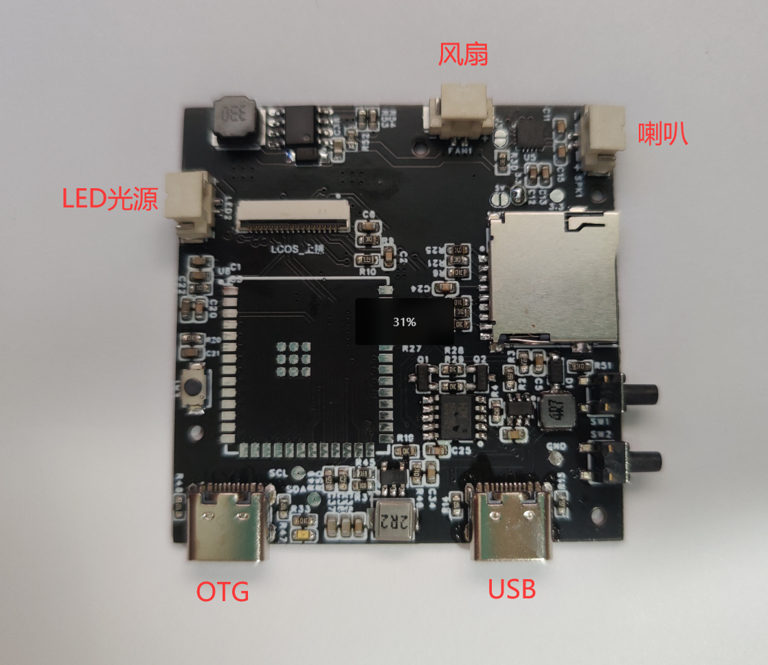
If your computer displays a message indicating excessive USB port current during firmware flashing, please connect the charging adapter to the OTG port and then connect the USB port to the computer.

Projection distance:
To project the entire area of an A4 sheet of paper, the distance is approximately 60cm.

The minimum projection distance is approximately 29cm (with the focus ring turned to the far left).
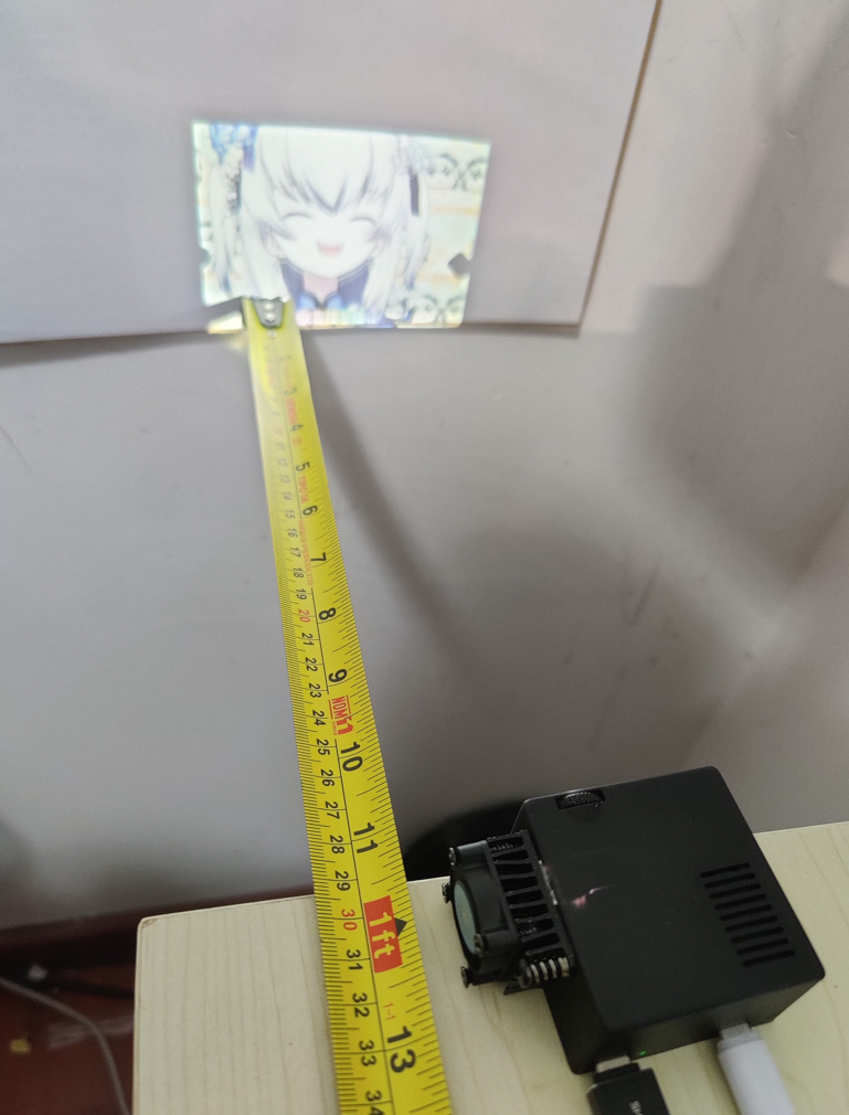
The maximum projection distance should be between 1m and 1.5m (with the focus ring turned to the far right). At this distance, the projected area will be slightly larger than the A3 size (29.7cm × 42.0cm), but the brightness will be lower.
For secondary development, please note:
The SD card slot is only compatible with SDMMC 1-bit mode. If you do not know how to use it, please refer to the example file in the attachment.
The R10 resistor can be replaced with any resistance value between 100-500K.
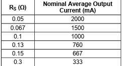
The current light source current is currently set to 760mA, and the brightness is acceptable. If you want to increase the current, you can replace it with the R52 resistor. The resistance value calculation formula is: R = 0.1 / backlight current (A).
Component purchase:
The BOM (Bill of Materials) has been matched with the C-number from LCSC's online store. You can also purchase them individually from Taobao.
The following items are not available in the online store and need to be purchased from Taobao
: Main controller: https://item.taobao.com/item.htm?id=676604026231 Specifications: S3-WROOM-1U-N8R8
Buttons: https://item.taobao.com/item.htm?id=617002359193 Specifications: 7mm from base to handle Tape-and-reel
speaker: https://item.taobao.com/item.htm?id=684864879619 Specifications: 2030 cavity, 4Ω, 3W
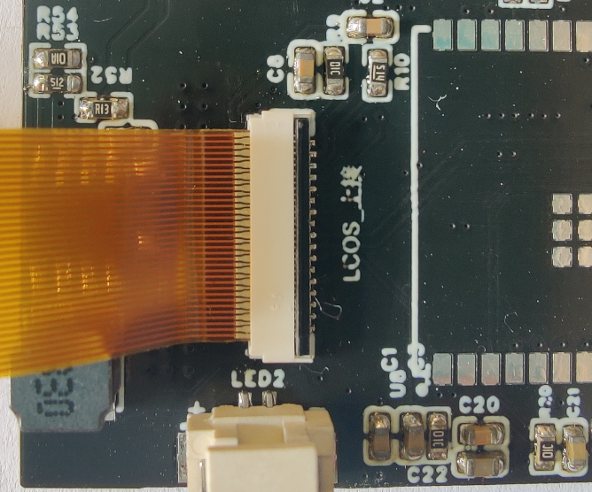
ribbon cable connector: https://item.taobao.com/item.htm?id=663268066843 Specifications: 0.3mm Front-plug, rear-lock (this connector is top-to-bottom)
ribbon cable: https://item.taobao.com/item.htm?id=729164547096 Specifications: 60mm, 35P in the same direction. Note: If the connector is bottom-plug, use reverse-direction mounting
screws: https://item.taobao.com/item.htm?id=539731606451 Specifications: M1.6*6*3.4 head*0.8mm thick
antenna: https://item.taobao.com/item.htm?id=586583930371 Specifications: 6cm IPEX 1st generation N types
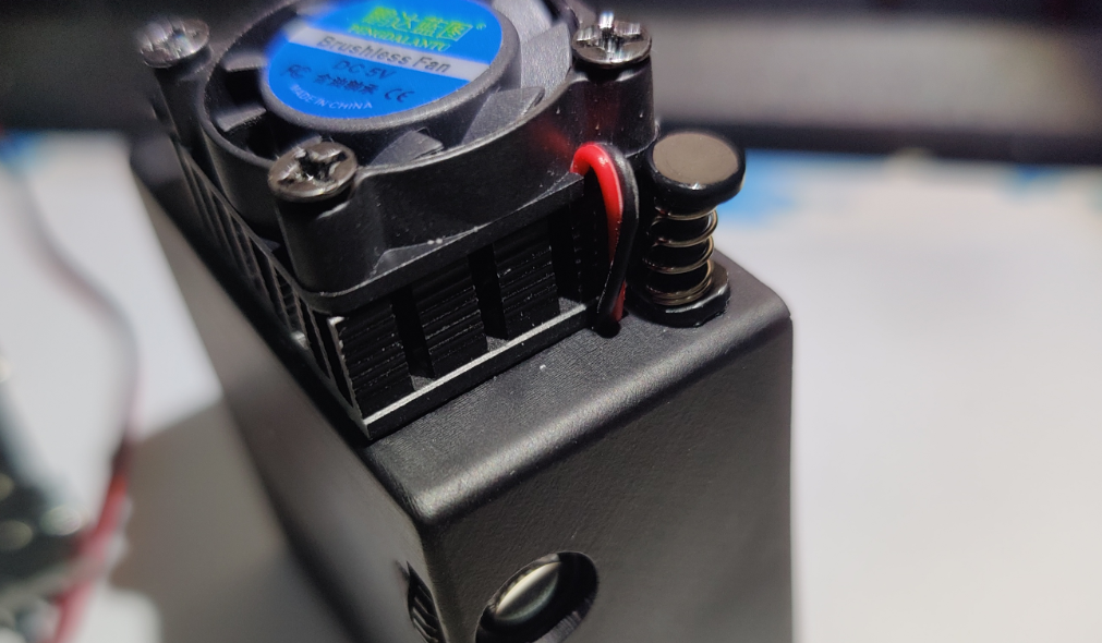
of cooling fans: https://item.taobao.com/item.htm?id=678659741079 Specifications: 2507 + thick aluminum sheet (5V with oil) 2.54
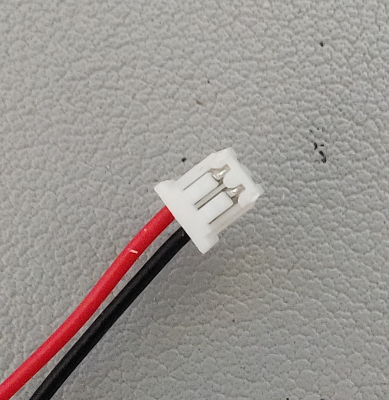
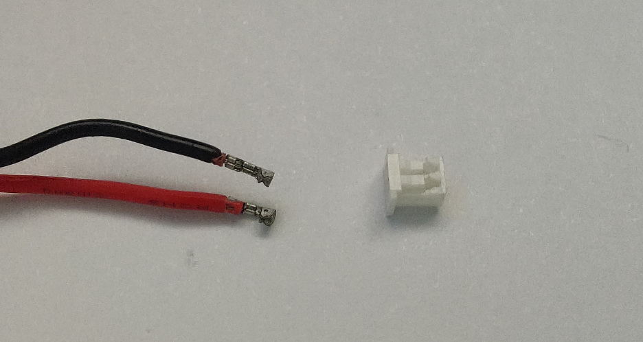
Note: After placing the order, contact customer service and say you need a 1.25mm pitch connector. Then send the picture below to customer service.
If the contact surface of the fan's heat sink aluminum block is uneven, you can use a hammer to flatten it.
Installation:
Note: Once the optical engine is installed in the housing, it is difficult to remove unless the housing is damaged.
Prepare an MX 1.25mm pitch 2P male connector and connect the optical engine's LED light source cable to the
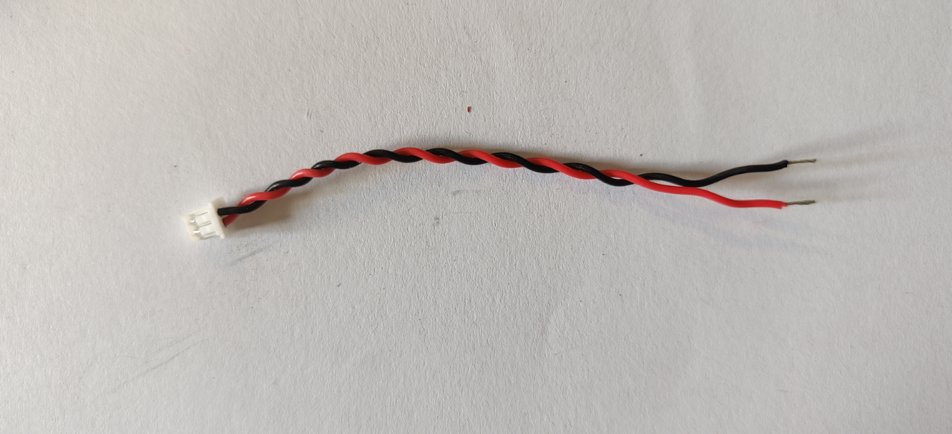
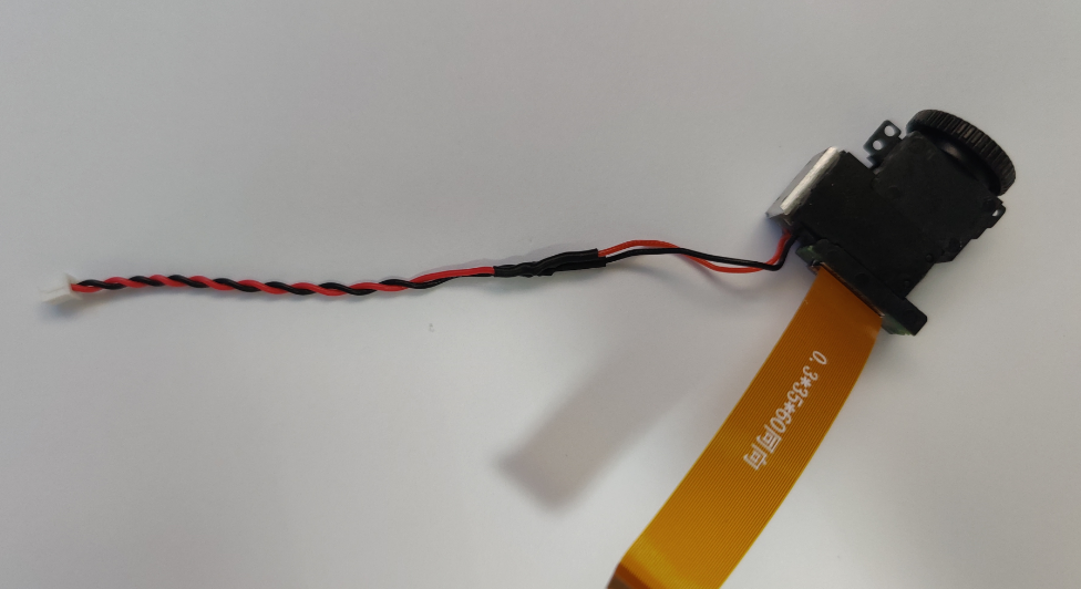
optical engine ribbon cable. Installation: (The optical engine ribbon cable must be installed first). After installation, manually fold the ribbon cable upwards

and then peel off the protective film on the optical engine lens
. (Carefully check the housing for any unpolished support points. If there are any, polish them smooth, otherwise they will block the optical engine.)
Place the optical engine diagonally into the housing
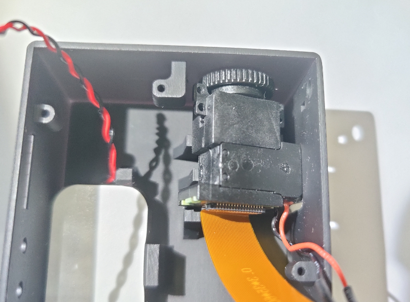
and push it to the right while pressing it down
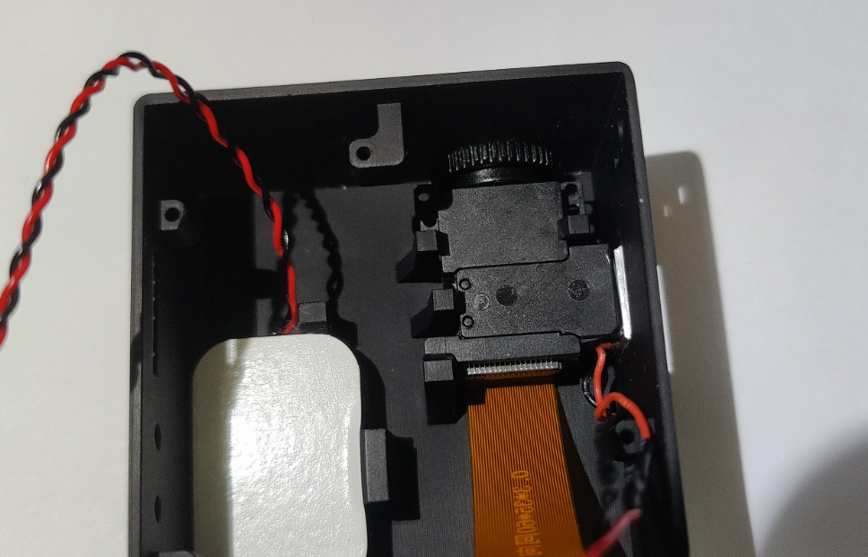
. Place the speaker diagonally in as well.
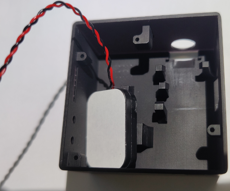
Then, while pushing to the left, press down firmly on

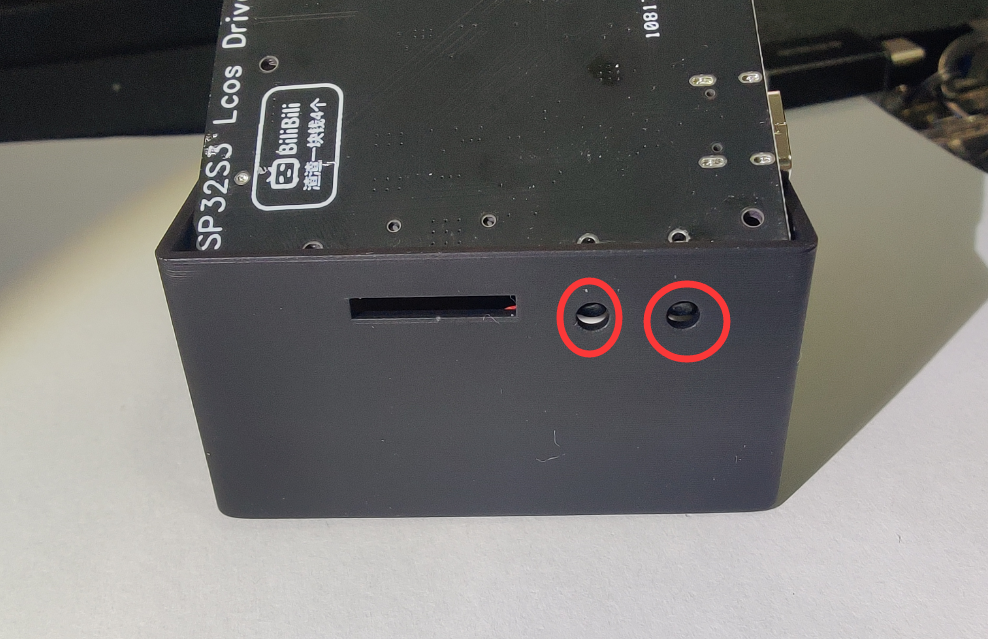
the heatsink connector. Use pointed tweezers or a needle to remove the terminal

, then insert it through the pre-drilled hole on the casing
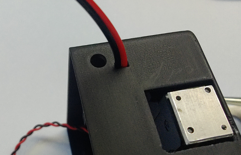
and back in (be careful not to reverse the positive and negative terminals) .

Apply thermal paste to the contact points between the heatsink and the optical engine, then align it with the hole on the side and press in the included adhesive pins to secure it.
Motherboard connection method: (By default, the gold fingers of the ribbon cable face up. If the connector is bottom-mounted, the ribbon cable is reversed, and the gold fingers face down.)
Then connect the other cables. Align
the two buttons
, then gently bend the right side of the casing to the right to insert the motherboard.

After inserting it, close the back cover and secure it with the four screws.
If the image is blurry during use, you can adjust the focus by turning this knob left
and right. Turn it to the left when you are closer, and turn it to the right when you are farther away.

Firmware:
There are two firmware files, one for the Arduino IDE example
. Firmware 1:
Game Console Firmware
Main functions: NES game emulator + MJPEG video player
Author: Twilight of Sanalan Bilibili Homepage: https://space.bilibili.com/18598545
Firmware open source address: https://github.com/planevina/esp32s3_nes_gamer
Note: The original GitHub project could only play video, not audio, when playing MJPEGs. Don't ask why.
Usage:
You need to download and unzip the "Game Console Memory Card Files.zip" compressed package in the attachment, and put the folders inside into the memory card. The memory card needs to be formatted as FAT32.
Folder structure:
NES folder: This folder is used to store NES game files. Theoretically, .nes game files are supported, but actual testing is required; opening.mp3 file is the boot sound effect.
MJPEG folder: This folder is used to store the MJPEG files to be played and audio.
Control method:
USB controller: A USB controller that costs a few yuan on Taobao will do. You need to bring your own USB to Type-C adapter. (Recommended: https://item.taobao.com/item.htm?id=599716798406)
Video playback requires conversion to .mjpeg files. Conversion instructions are below.
Video and audio files must have the same filename, i.e., 001.mjpeg 001.mp3.
Game controller operation:
Joystick up, down, left, right;
A for confirmation; B for returning to
the game. Press both Select and Start buttons simultaneously to exit to the main menu.
In the main menu, press B to enable mute mode.
In the video list, press A to play the selected video.
While the video is playing, press B to return to the video list.
During playback, the up arrow key increases volume, and the down arrow key decreases volume. The default volume is 50%, and the volume adjustment range is 5%~100%.
Firmware 2:
Under development...
Example 1:
Video playback demo
(Firmware attached)
This example is only provided for reference by those who want to write their own firmware, that is, how to drive this projection module using the Arduino_GFX library.
It is modified from the Arduino_GFX library example, original link: https://github.com/moononournation/MiniTV/tree/master/ZX3D50CE02S.
These three libraries are needed
: https://github.com/moononournation/Arduino_GFX, https://github.com/pschatzmann/arduino-libhelix, and https://github.com/bitbank2/JPEGDEC.
The modified files are in the attachment
. The conversion method is below.
Firmware burning:
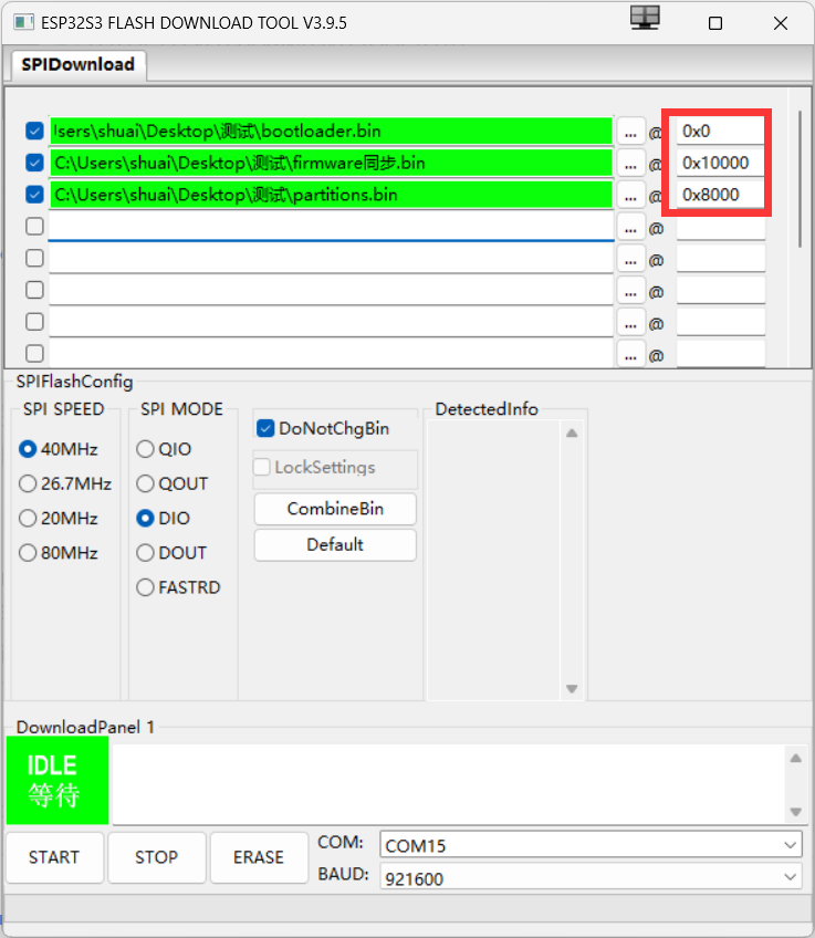
Open flash_download_tool_3.9.5.exe
, select ESP32S3

, select each partition file:
bootloader.bin (burning address 0x0),
firmware.bin (burning address 0x10000),
partitions.bin (burning address 0x8000).
Connect the Type-C data cable to the USB port (do not connect to the OTG port). The CH340 driver needs to be installed beforehand. Then select your serial port number, click START to start burning
, wait for the progress bar to complete, then unplug the data cable and plug in a charger with a voltage of 5V2A or higher
. (Do not use your computer's USB port to power it; the peak power is 6.5W+, use a charger with a voltage of 5V2A or higher).
Video conversion:
Since the video being played uses MJPEG image frames, FFmpeg is needed for conversion.
FFmpeg download address: https://ffmpeg.org or download directly from Github: https://github.com/BtbN/FFmpeg-Builds/releases.
Usage: When exporting with your editing software, change the resolution to 320*240 pixels and export as a .mp4 file. Download and extract FFmpeg. In the FFmpeg.exe directory, hold down the Shift key, right-click, and select "Open PowerShell window here."
Execute the following command to convert the mp4 file to MJPEG format
: `./ffmpeg -i [your mp4 file path] -vf`. `"fps=25,scale=-1:240:flags=lanczos,crop=320:in_h:(in_w-320)/2:0" -q:v 5 [output path]`
For example: `
./ffmpeg -i D:video1.mp4 -vf "fps=18,scale=-1:240:flags=lanczos,crop=320:in_h:(in_w-320)/2:0" -q:v 5 D:video01.mjpeg`
After conversion, place the `001.mjpeg` file in the root directory of the memory card. The memory card needs to be formatted as FAT32.
Audio conversion:
`./ffmpeg -i [your mp4 file path] -ar 44100 -ac 1 -ab 32k -filter:a loudnorm -filter:a "volume=-5dB" [output path]` For example: `./ffmpeg -i` D:video1.mp4 -ar 44100 -ac 1 -ab 32k -filter:a loudnorm -filter:a "volume=-5dB"
After converting D:video01.mp3, simply place the 001.mp3 file in the root directory of your memory card
. Finally finished writing!
(Group chat: 636426429)

Firmware flashing tool_flash_download_tool_3.9.5_2.zip
HX7033 Manual (Incomplete).pdf
Game console firmware.zip
Game console memory card file.zip
Example 1.zip
video.mp4
Shell.zip
PDF_ESP32S3 LCOS Small Projector.zip
Altium_ESP32S3 LCOS Small Projector.zip
PADS_ESP32S3 LCOS Small Projector.zip
BOM_ESP32S3 LCOS Small Projector.xlsx
91025
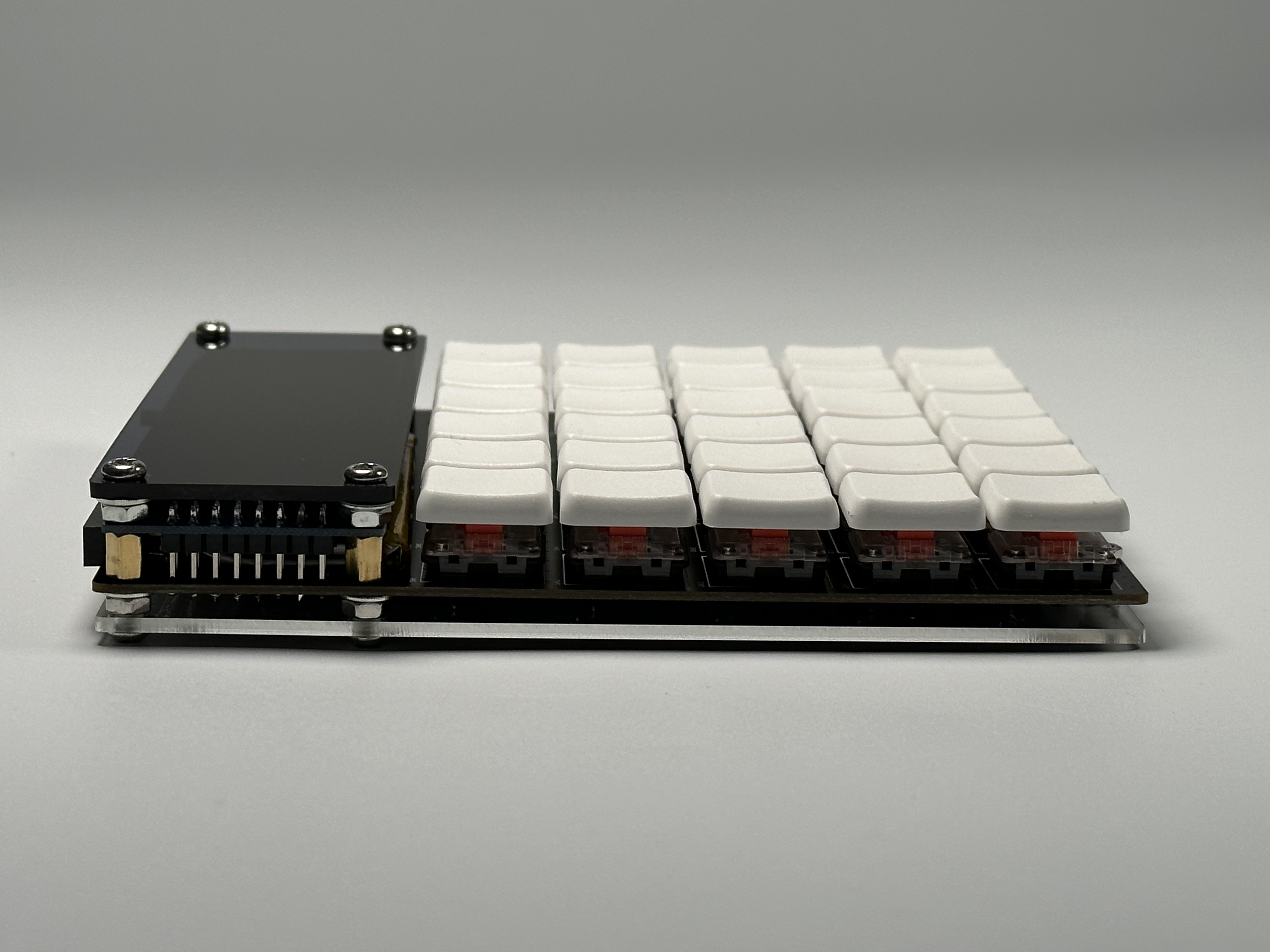
Multifunctional Mechanical Shaft Scientific Calculator
Calculator + Numeric Macro Keyboard + Handheld Game Console + Full-Powered Development Board (4-in-1)
This project documentation will be continuously updated.
Overview:
This is a multi-functional calculator that combines a scientific calculator, numeric macro keyboard, handheld game console, and a fully functional development version into one device. Initially, I started making my own calculator because I found the calculator software purchased by the school to be bloated, cumbersome, and difficult to use (Ti-Nspire, cough cough). However, I later added a bunch of other functions, and it became what it is now. (For more information, please see https://github.com/shaoxiongduan/sci-calc/) Bilibili
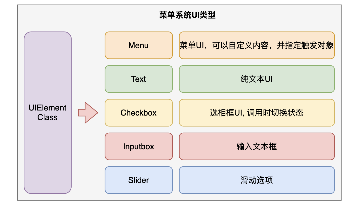
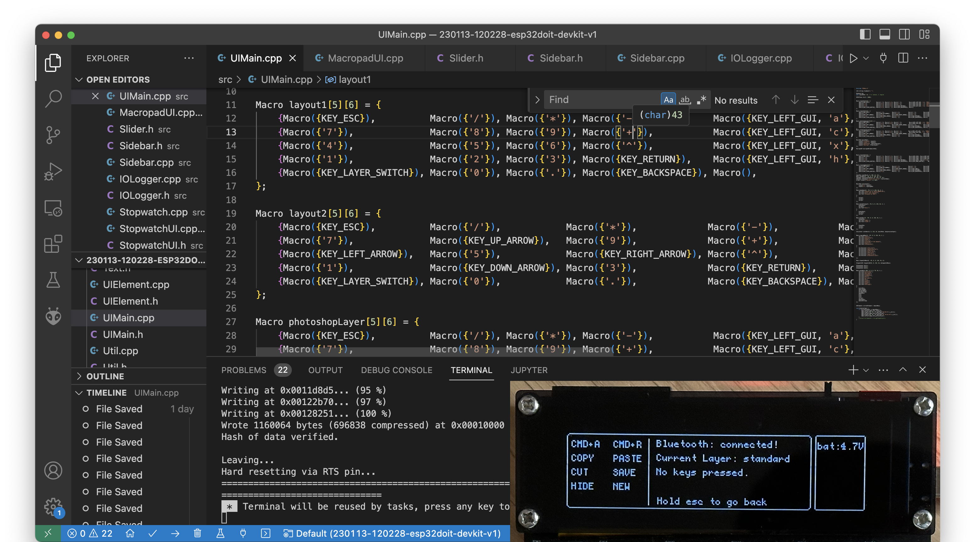
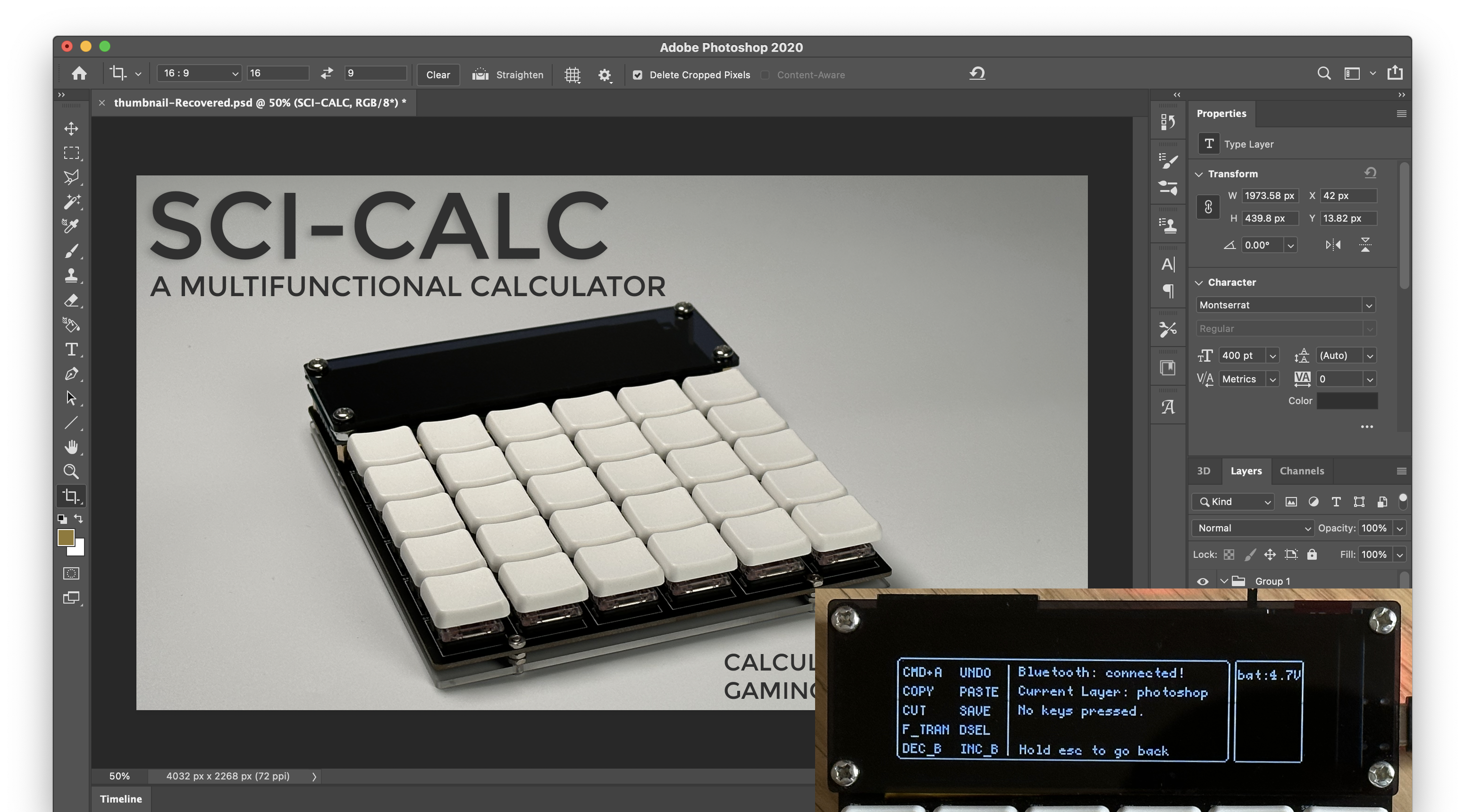
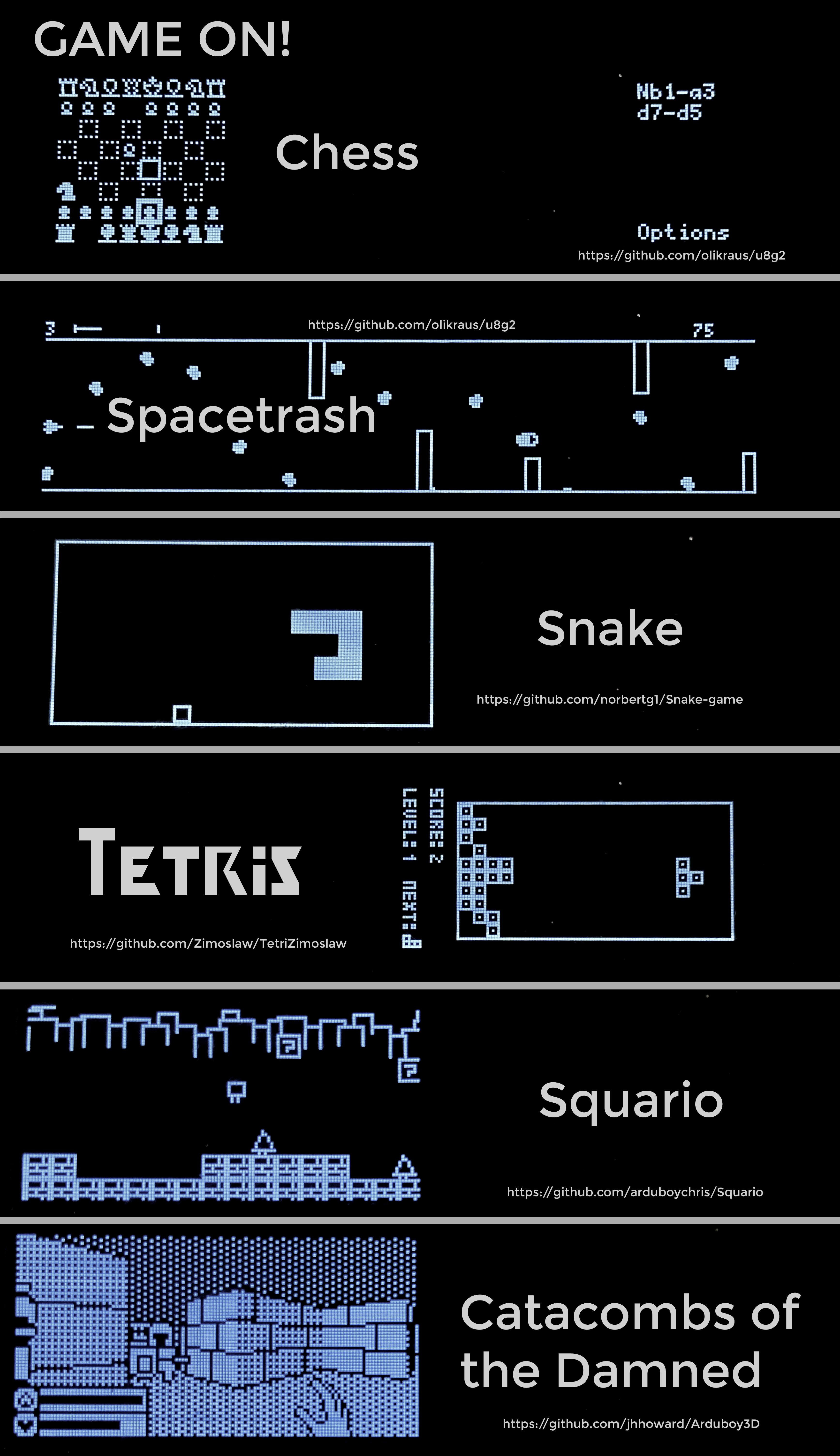
Collection Configuration : ESP32 WROOM32 E Driver Switches: Kailh v1 choc Low-profile switches Screen: 256x64 OLED (SSD1322) Serial Port Chip: CH340C 1000mAh Battery + TP4056 + DW01 Battery Protection, supports simultaneous charging and use Supports microSD card storage Program Firmware Menu System and UI Components Macro Keyboard Program The macro keyboard program is also quite intuitive. Custom macro keys can be built through the following methods. The 10 buttons in the two columns on the right will automatically appear on the screen as the main macro keys. Customize one layer of buttons: Macro layout1[5][6] = { {Macro({'7'}), Macro({'8'}), Macro({'9'}), Macro({'+'}), Macro({KEY_LEFT_GUI, 'c'}, "COPY"), Macro({KEY_LEFT_GUI, 'v'}, "PASTE")}, {Macro({KEY_ESC}), Macro({'/'}), Macro({'*'}), Macro({'-'}), Macro({KEY_LEFT_ALT, KEY_LEFT_GUI, 'c'}, "C_PATH"), Macro({KEY_LEFT_GUI, 'r'}, "CMD+R")}, {Macro({'4'}), Macro({'5'}), Macro({'6'}), Macro({'^'}), Macro({KEY_LEFT_GUI, 'x'}, "CUT"), Macro({KEY_LEFT_GUI, 's'}, "SAVE")}, {Macro({'1'}), Macro({'2'}), Macro({'3'}), Macro({KEY_RETURN}), Macro({KEY_LEFT_GUI, 'h'}, "HIDE"), Macro({KEY_LEFT_GUI, 'n'}, "NEW")}, {Macro({KEY_LAYER_SWITCH}), Macro({'0'}), Macro({'.'}), Macro({KEY_BACKSPACE}), Macro({KEY_F12}, "G_DEC"), Macro()} }; Initialize macro keyboard class: MacroPad macroPad({ Layout("standard", layout1), Layout("layout 2", layout2), Layout("photoshop", photoshopLayer), Layout("editing", filmoraLayer), Layout("obsidian", obsidianLayer) }); MacropadUI MacropadUI (& MacroPad); The calculator firmware is developed using VS Code + PlatformIO. All programs and configuration files are on GitHub: After flashing the program to the ESP32, it won't run immediately upon boot. You need to copy the .bin file from the SD card. Function keys: Toggle key layers: /Shift: Single press temporarily toggles, double press toggles and locks like the Shift key, angle toggle key: Toggles between angle and radian units. Tab: Used to switch between the calculator input box and history. Appearance: The calculator 's appearance is made of stacked acrylic sheets, mainly composed of a black semi-transparent acrylic sheet + PCB + a transparent acrylic sheet at the bottom. It is very sturdy, inexpensive, and easy to assemble; users have praised it. The UI calculator supports basic arithmetic operations, including square roots, trigonometric functions, and exponential/logarithmic functions. Automatic differentiation and equation solving may be added in the future. History: Used to record calculations. You can also copy the answers from the history using Tab + Enter, greatly improving calculation efficiency and eliminating the need to manually type out previously calculated formulas. This calculator also functions as a numeric keypad with 10 customizable macro keys. The defined keys are displayed on the left side of the screen. Multiple macro keys can be set, allowing you to switch between different levels depending on the software you're using, such as for programming . (PS: There's also editing: Uploading programs involves saving the compiled program's .bin file to a microSD card, and the calculator reads and runs the file.) To improve learning efficiency and motivation, I've ported several "learning software" tools from various developers: An ESP32 development version calculator brings out the ESP32 pins, allowing it to be used as a development board with Arduino IDE. These pins can also be connected to expansion modules (I'm too lazy to design them yet). Please like and follow! :)


main.bin
COTD.bin
squario.bin
chess.bin
snake.bin
spacetrash.bin
tetris.bin
Calculator demo.m4v
All Code.zip
Game demo.mp4
PDF_Multifunctional Mechanical Shaft Scientific Calculator.zip
Altium_Multifunctional Mechanical Shaft Scientific Calculator.zip
PADS_Multifunctional Mechanical Axis Scientific Calculator.zip
BOM_Multifunctional Mechanical Shaft Scientific Calculator.xlsx
91026
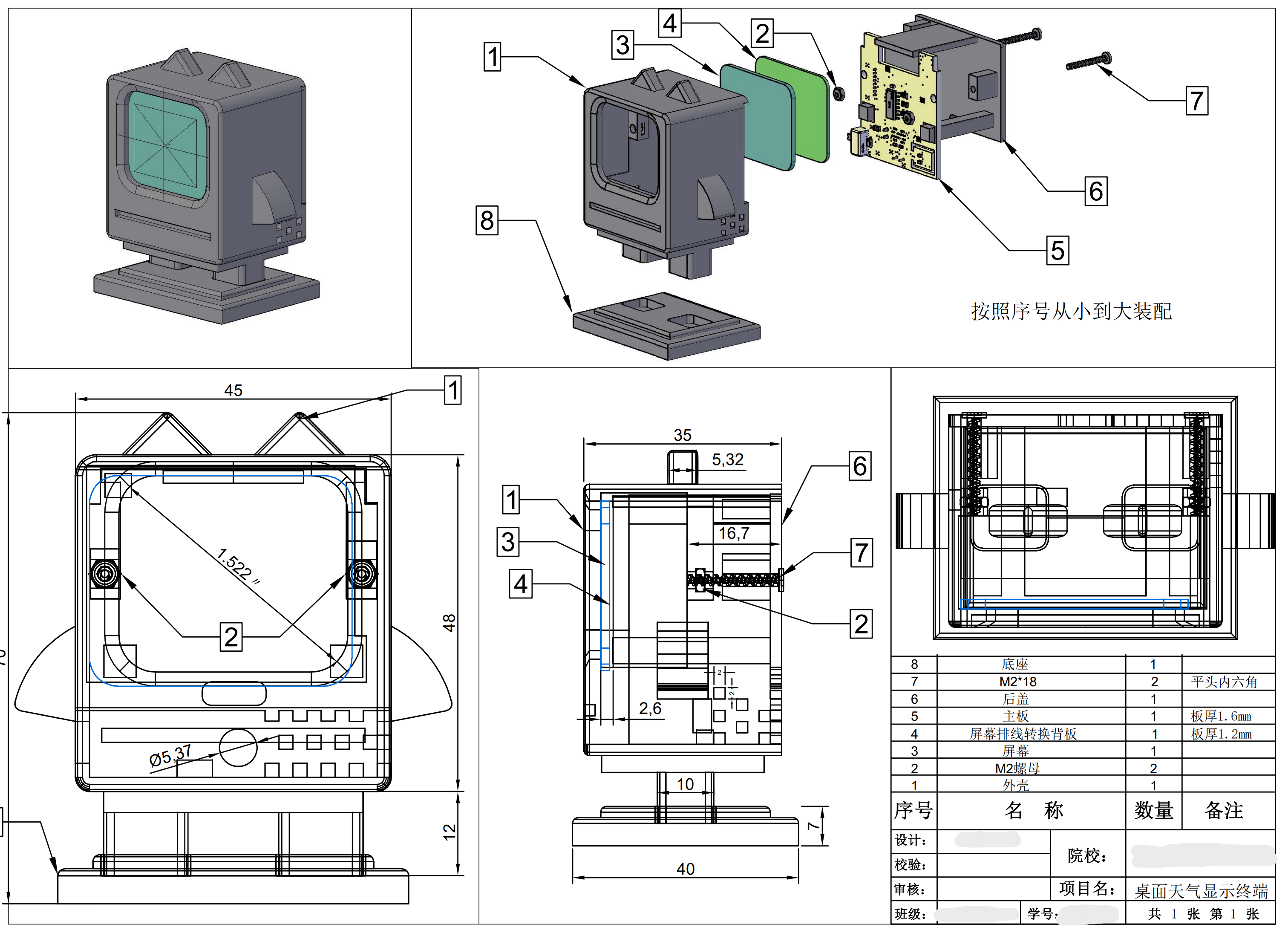
ESP32_32E Desktop Weather Terminal
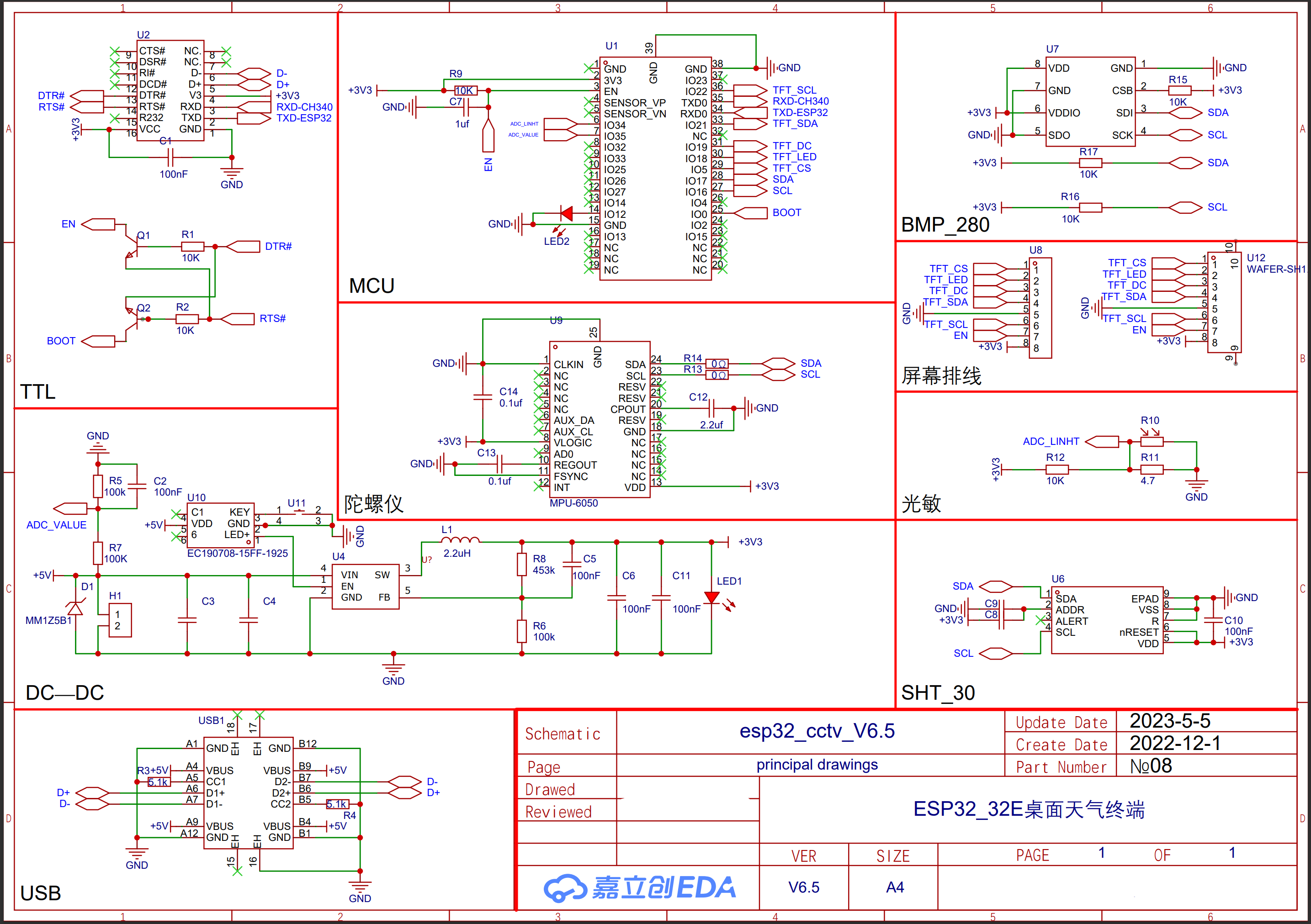
Using the ESP32-WROOM_32E main control chip, the local sensors employ two temperature, humidity and barometric pressure sensors, SHT30 and BMP280, to detect and display local temperature data in real time. The main control chip is connected to the network and automatically obtains its location and weather conditions via IP.
ESP32 Multifunctional Time and Weather Desktop Display Terminal
Project Introduction: This project uses the ESP32-WROOM series domestic WiFi chip as the main control chip. Local sensors, specifically the SHT30 and BMP280 temperature, humidity, and barometric pressure sensors, are used to detect and display local temperature data in real time. The main control unit automatically obtains its location and weather conditions via IP address. The built-in light sensor automatically adjusts the screen brightness based on ambient light intensity and features OTA remote firmware upgrade functionality.

#### Shell Design
#### Circuit Design
#### Library Installation Method and Compilation Tutorial
1. Download and install Arduino IDE 1.8.19 (https://www.arduino.cc/en/software)
2. Unzip the files in the software program/Arduino-libraries directory and place them in the Arduino IDE 1.8.19/libraries directory.
3. Unzip the files in the software program/libraries directory and place them in the Arduino Library directory of your system documentation.
For example: C:\Users....your username.....Documents\Arduinolibraries
. If this path does not exist, run the example in the IDE first and then check it.
4. Download the ESP32 development board from the Arduino IDE 1.8.19 software.
5. Select the development board in the tools options (as shown in the image).

6. Open the file `/arduinoIDE_minicctv_main_ino/arduino_IDE_cctv.ino` and compile it. If there are no errors, the first four steps are correct.
#### Instructions for Use
1. **Connecting to WiFi:** For first-time use, you need to connect to your own WiFi network.
1.1: After powering on, wait for the WiFi connection timeout screen to appear.
1.2: Turn on your phone or computer's WiFi and search for and connect to WiFi networks starting with `ESP32`
. 1.3: In the pop-up window, select the WiFi name and enter the WiFi password.
1.4: Click Save and wait for the module to connect to WiFi.
2. **Online Firmware Update**
2.1: Contact the administrator and provide the device serial number
. 2.2: Wait for the administrator to upload the firmware. 2.3
: Restart the device after the firmware upload is complete.
2.4: The device will automatically connect to the internet and update the firmware after restarting. Just wait.
#### All files are open source. This project, without my authorization, must comply with the **GNU General Public License** open source agreement. **[Commercial use prohibited]** For the complete project files, please contact the author via
email: **trustedzxz@outlook.com**
or QQ: 226885396
PDF_ESP32_32E Desktop Weather Terminal.zip
Altium_ESP32_32E Desktop Weather Terminal.zip
PADS_ESP32_32E Desktop Weather Terminal.zip
BOM_ESP32_32E Desktop Weather Terminal.xlsx
91027
STM32-based mechanical four-jaw jack
A simple mechanical quadruped based on STM32F103C8TC.
Preface:
While browsing Bilibili, I stumbled upon a mechanical quadruped made by a content creator, which inspired me to make a simplified version. Please excuse its simplicity.

Materials needed:
1. One STM32F103C8T6 development board

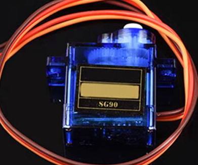
2. Eight blue SG9 classic 180-degree servos
3. One IIC communication OLED screen (large or small)

4. One 3.7V lithium battery + one 5V lithium battery Alternatively, you can use my lazy method: directly using the ST-Link power supply
schematic and PCB design instructions.
The design consists of four parts: power supply, OLED, servos, and STM32 board.
1. The power supply
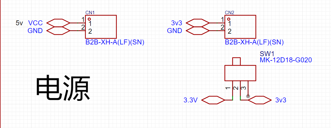
only requires a miniature toggle switch + two 2P headers or sockets. Alternatively, you can just place the pads and then connect the batteries with jumper wires.
Use the miniature toggle switch to control the power supply to the STM32 board.
The 3V power supply is for the STM32F103C8T6 board and can be powered by a small 3.7V lithium battery.
The 5V power supply is for the servos and can be powered by a 5V lithium battery.
Two batteries can be glued to the bottom of the base plate using a hot glue gun.
Of course, for lazy people like me, I can directly use the 3V3 and 5V drivers on the ST-Link, and I can modify the code at any time.

2. The I2C communication port of the OLED screen
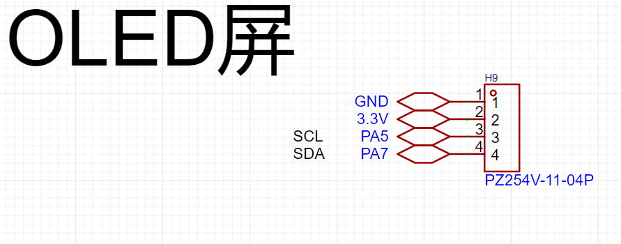
only needs a 4-pin header.
The screen I used here can be driven by 3V3, but you can also switch to 5V depending on the application.
The communication ports SC1 and SDA use PA5 and PA7 I/O ports respectively (this is how the code is written), and you can change them according to your own code.
If you are using other communication methods, this part needs to be modified accordingly.
3.
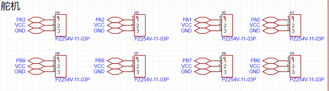
The reason for using these ports for the servo part is that the distance is short, and the subsequent wiring is simple.
Secondly, when writing the code to control the servo, you need to consider the TIM clock. The following figure shows the I/O port corresponding to the TIM clock of the STM32. 4. For
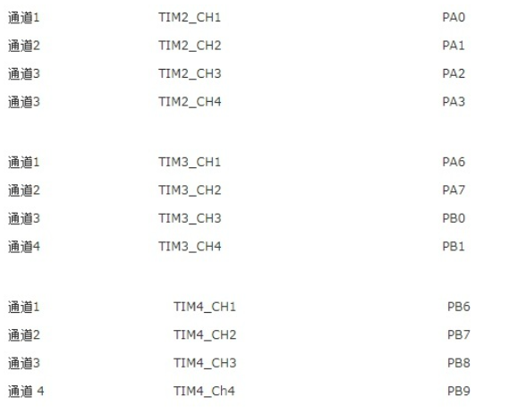
the STM32F103C8T6
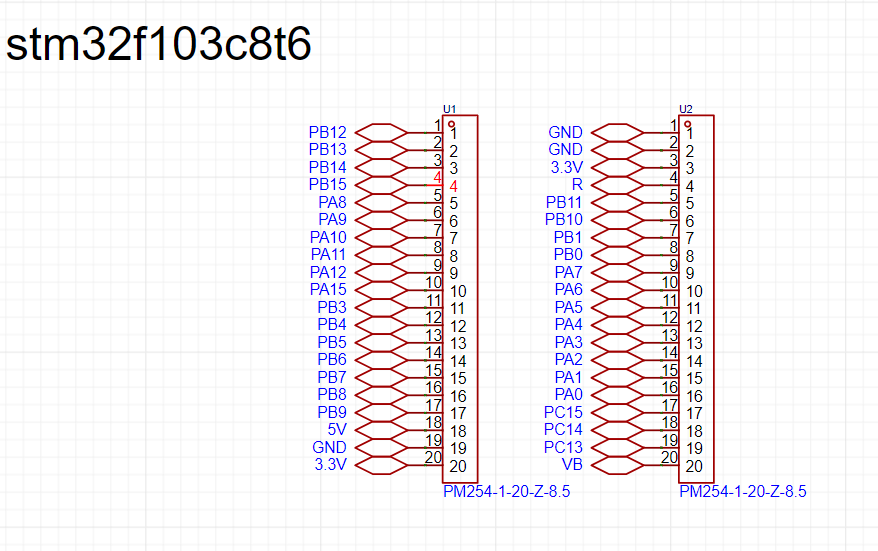
, I used female headers to draw each serial port of the STM32.
In the PCB, you need to pay attention to the spacing of the female headers, otherwise they will not fit.
The code section explains that
Keil 5 was used for programming. In fact, you only need to write the PWM file here. For OLED, you can just copy the header file that has been compiled online.
The PWM section
requires checking the STM32's TIM clock table.
I've chosen TIM2 and TIM4, so I need to define the I/O ports PA0, 1, 2, 3 and PB6, 7, 8, 9: `
void Pwm_Init_TIM2(void)
{
GPIO_InitTypeDef GPIO_InitTypeStruce
; TIM_TimeBaseInitTypeDef
TIM_TimeBaseInitTypeStruce;
TIM_OCInitTypeDef TIM_OCInitTypeStruce; RCC_APB2PeriphClockCmd(RCC_APB2Periph_GPIOA,ENABLE);//Enable the PA serial port and reuse the TIM2 clock
RCC_APB2PeriphClockCmd(RCC_APB2Periph_AFIO,ENABLE);
RCC_APB1PeriphClockCmd(RCC_APB1Periph_TIM2,ENABLE);`
GPIO_InitTypeStruce.GPIO_Mode=GPIO_Mode_AF_PP; // Set push-pull output
GPIO_InitTypeStruce.GPIO_Pin=GPIO_Pin_0|GPIO_Pin_1|GPIO_Pin_2|GPIO_Pin_3; // Define PA0, PA1, PA2, PA3 serial ports
GPIO_InitTypeStruce.GPIO_Speed=GPIO_Speed_50MHz;
TIM_TimeBaseInitTypeStruce.TIM_Period=1999; // The PWM period should be 20ms = (720*2000)/72000000=0.02
TIM_TimeBaseInitTypeStruce.TIM_Prescaler=719; // So I take the values 2000-1 and 720-1 respectively
TIM_TimeBaseInitTypeStruce.TIM_ClockDivision=0;
TIM_TimeBaseInitTypeStruce.TIM_CounterMode=TIM_CounterMode_Up;
TIM_OCInitTypeStruce.TIM_OCMode=TIM_OCMode_PWM1; //This sets the PWM mode.
TIM_OCInitTypeStruce.TIM_OutputState=TIM_OutputState_Enable;
TIM_OCInitTypeStruce.TIM_OCPolarity=TIM_OCPolarity_High;
GPIO_Init(GPIOA,&GPIO_InitTypeStruce); //The following initializes the four serial ports.
TIM_TimeBaseInit(TIM2,&TIM_TimeBaseInitTypeStruce);
TIM_OC1Init(TIM2,&TIM_OCInitTypeStruce);
TIM_OC2Init(TIM2,&TIM_OCInitTypeStruce);
TIM_OC3Init(TIM2,&TIM_OCInitTypeStruce);
TIM_OC4Init(TIM2,&TIM_OCInitTypeStruce);
TIM_OC1PreloadConfig(TIM2,TIM_OCPreload_Enable); // The following enables the clock for TIM2:
TIM_OC2PreloadConfig(TIM2,TIM_OCPreload_Enable);
TIM_OC3PreloadConfig(TIM2,TIM_OCPreload_Enable);
TIM_OC4PreloadConfig(TIM2,TIM_OCPreload_Enable);
TIM_Cmd(TIM2,ENABLE);
}
void Pwm_Init_TIM4(void) //TIM4 is similar to TIM2 in its settings, but GPIOA should be changed to GPIOB, TIM2 to TIM4, and the four serial ports should also be modified
{
GPIO_InitTypeDef GPIO_InitTypeStruce;
TIM_TimeBaseInitTypeDef TIM_TimeBaseInitTypeStruce;
TIM_OCInitTypeDef TIM_OCInitTypeStruce;
RCC_APB2PeriphClockCmd(RCC_APB2Periph_GPIOB,ENABLE);
RCC_APB2PeriphClockCmd(RCC_APB2Periph_AFIO,ENABLE);
RCC_APB1PeriphClockCmd(RCC_APB1Periph_TIM4,ENABLE);
GPIO_InitTypeStruce.GPIO_Mode=GPIO_Mode_AF_PP;
GPIO_InitTypeStruce.GPIO_Pin=GPIO_Pin_6|GPIO_Pin_7|GPIO_Pin_8|GPIO_Pin_9;
GPIO_InitTypeStruce.GPIO_Speed=GPIO_Speed_50MHz;
TIM_TimeBaseInitTypeStruce.TIM_Period=1999;
TIM_TimeBaseInitTypeStruce.TIM_Prescaler=719;
TIM_TimeBaseInitTypeStruce.TIM_ClockDivision=0;
TIM_TimeBaseInitTypeStruce.TIM_CounterMode=TIM_CounterMode_Up;
TIM_OCInitTypeStruce.TIM_OCMode=TIM_OCMode_PWM1;
TIM_OCInitTypeStruce.TIM_OutputState=TIM_OutputState_Enable;
TIM_OCInitTypeStruce.TIM_OCPolarity=TIM_OCPolarity_High;
GPIO_Init(GPIOB,&GPIO_InitTypeStruce);
TIM_TimeBaseInit(TIM4,&TIM_TimeBaseInitTypeStruce);
TIM_OC1Init(TIM4,&TIM_OCInitTypeStruce);
TIM_OC2Init(TIM4,&TIM_OCInitTypeStruce);
TIM_OC3Init(TIM4,&TIM_OCInitTypeStruce);
TIM_OC4Init(TIM4,&TIM_OCInitTypeStruce);
TIM_OC1PreloadConfig(TIM4,TIM_OCPreload_Enable);
TIM_OC2PreloadConfig(TIM4,TIM_OCPreload_Enable);
TIM_OC3PreloadConfig(TIM4,TIM_OCPreload_Enable); After writing the PWM initialization file, we can use the following functions for duty cycle control:
TIM_OC4PreloadConfig(TIM4,TIM_OCPreload_Enable); TIM_Cmd ( TIM4,ENABLE)
;
} Similarly, we still rely on the TIM clock , e.g.: TIM_SetCompare3(TIM2,50); // This means that the third serial port on the TIM2 clock (see the TIM clock table above), PA2, controls the servo to rotate to the 0° position. TIM_SetCompare2(TIM4,250); // This means that the second serial port on the TIM4 clock (see the TIM clock table above), PB7, controls the servo to rotate to the 180° position. Here, 50 corresponds to the servo rotating to 0°, and 250 corresponds to the servo rotating to 180° , which means that the rotation degree of the servo can be controlled between 50 and 250. For information on using the OLED part, please refer to CSDN for usage instructions. Master the OLED display principle – Learn various OLED module usage methods_OLED Usage Methods - CSDN Blog. Modeling instructions and parameters: I used SolidWorks 2022. Servo hole size: After 3D printing, the material extrusion allows for direct use of 2mm screws. Foot hole size: Also, 2mm screws are sufficient. Leg connection: Because mirroring was used, some cutting is required when slicing. Installation precautions: You need to know the three servo wires: Yellow or orange is the signal wire, red is the power wire, and black or brown is the ground wire. First, you need to know how the servo rotates:


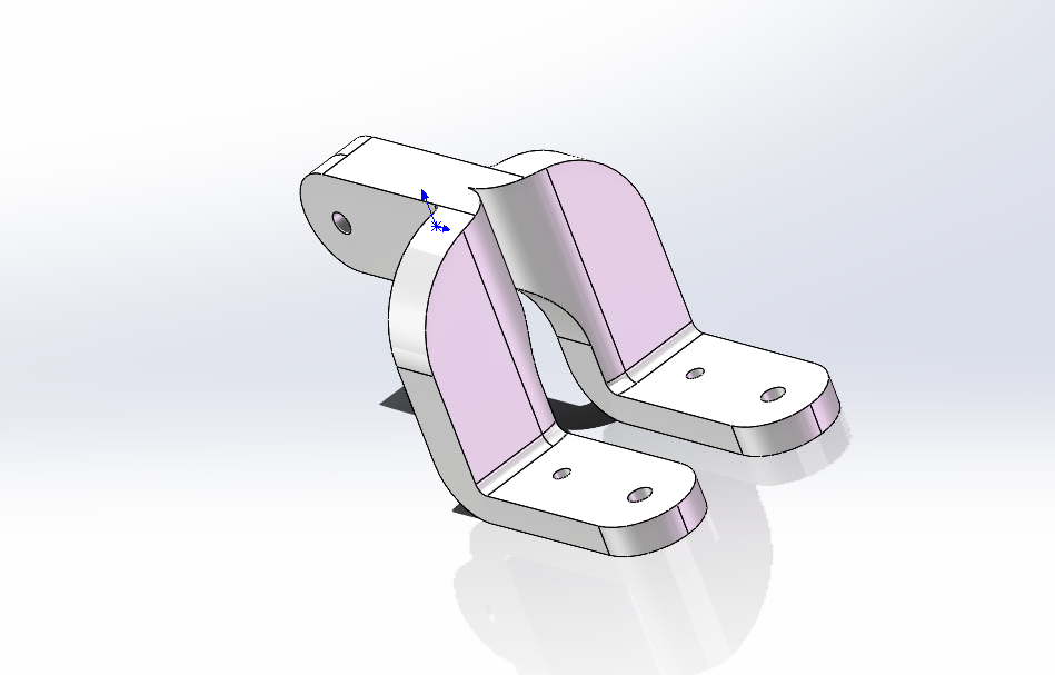
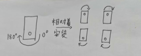
Before installation, you need to use code to rotate all the servos to 90° before fixing the legs. This increases the leg's freedom of movement.
First, use these codes:
`TIM_SetCompare1(TIM2,150);
TIM_SetCompare2(TIM2,150);
TIM_SetCompare3(TIM2,150);
TIM_SetCompare4(TIM2,150);
TIM_SetCompare1(TIM4,150);
TIM_SetCompare2(TIM4,150);
TIM_SetCompare3(TIM4,150);
TIM_SetCompare4(TIM4,150);`
to adjust the servos to 90°. Then connect the legs as shown in the diagram.
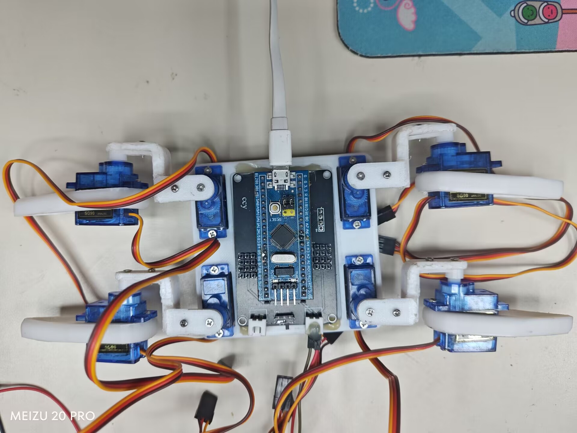
To run my code, connect the servo cables as shown in the diagram.

In summary
, since I'm still a university beginner, this is a very simple design. Please point out any problems. Thank you.
Mechanical four-jaw jack.jpg
Demonstration video.mp4
3D printing files.zip
Mechanical Quadruped Code.zip
PDF_STM32-based Mechanical Four-Jaw Machine.zip
Altium_STM32-based Mechanical Quad-Jaw.zip
PADS_STM32-based Mechanical Four-Jaw Machine.zip
BOM_STM32-based mechanical four-jaw jack.xlsx
91028
electronic


 京公网安备 11010802033920号

 36511-0098


